
Quick-split type H-shaped steel concrete beam column connection node

A beam-column connection and H-beam technology, which is applied in construction, building structure, and building material processing, etc., can solve the problems of high drilling positioning accuracy, decreased column stability after drilling, and concrete extrusion damage, etc. The effect of on-site construction efficiency, reduction of on-site welding volume, and improvement of bearing capacity and ductility

Pending Publication Date: 2019-06-21
XI'AN UNIVERSITY OF ARCHITECTURE AND TECHNOLOGY
View PDF0 Cites 3 Cited by
  • Summary
  • Abstract
  • Description
  • Claims
  • Application Information

AI Technical Summary

Problems solved by technology

However, the existing connection methods will bring many problems. For example, the installation of steel corbels will cause a sudden change in the cross-sectional bearing capacity and stiffness at the end, and concrete extrusion damage will easily occur. Decreased stability; the method of directly welding the longitudinal reinforcement to the connecting plate or the steel column will cause too many welding seams of the steel column, and the accumulation of welding residual stress will lead to the weakening of the section, thereby reducing the joint strength; steel bars of different strengths are welded to the steel , because of the different carbon content, the welding quality is affected, and the joint strength is also weakened

Method used


Image

  • Quick-split type H-shaped steel concrete beam column connection node
  • Quick-split type H-shaped steel concrete beam column connection node
  • Quick-split type H-shaped steel concrete beam column connection node

Examples


Embodiment Construction

[0028] The present invention is further described below in conjunction with accompanying drawing:

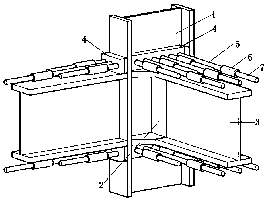
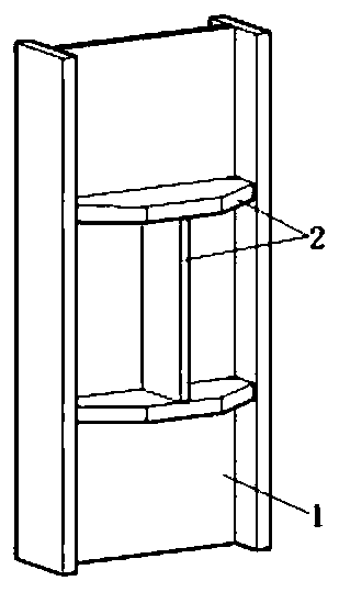
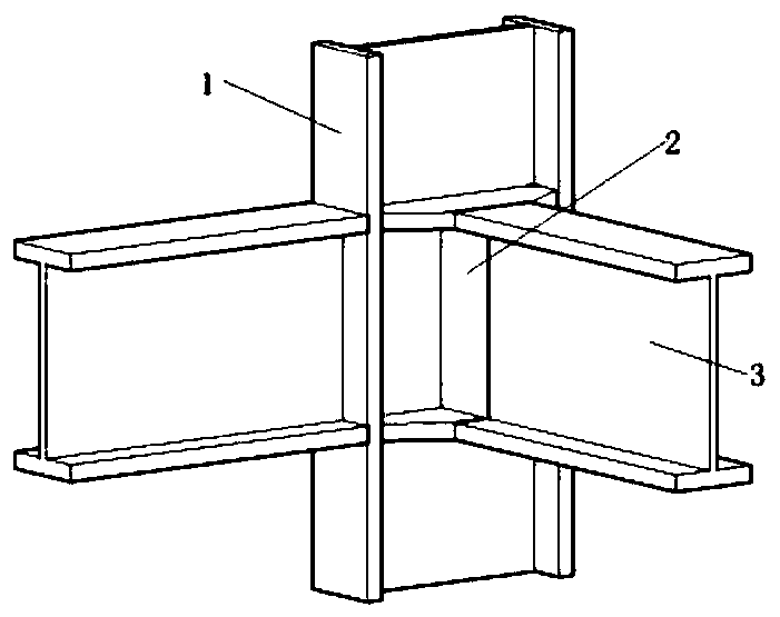
[0029] see Figure 1 to Figure 8 , a quick-assembled H-shaped steel concrete beam-column connection node, including H-shaped steel column 1, connecting plate 4, stiffening member 2, H-shaped steel beam 3 and reinforcing rib; any flange surface of H-shaped steel column 1 is fixed and vertically arranged There are H-shaped steel beams 3, connecting plates 4 are respectively fixed on the flanges of the H-shaped steel columns 1 at the contact points between the upper and lower flanges of the H-shaped steel beams 3 and the flanges of the H-shaped steel columns 1; any one of the H-shaped steel columns 1 H-shaped steel beams 3 are vertically fixed on the side web through stiffening members 2, and connecting plates 4 are arranged on the webs of H-shaped steel columns 1 at both ends of the stiffening member 2; several threaded holes are arranged on the connecting plates 4, and the connec...


PUM


Abstract

The invention relates to a quick-split type H-shaped steel concrete beam column connection node, comprising H-shaped steel columns, connecting plates, stiffening members, H-shaped steel beams and reinforcing ribs, wherein the H-shaped steel beam is fixedly and vertically arranged on any flange surface of each H-shaped steel column; the connecting plates are respectively and fixedly arranged at theflanges of the H-shaped steel columns at the parts where the flanges of the H-shaped steel columns are contacted with upper and lower flanges of the H-shaped steel beams; the H-shaped steel beams arevertically and fixedly arranged on webs at any sides of the H-shaped steel columns by means of the stiffening members; the webs of the H-shaped steel columns at the two ends of the stiffening membersare respectively provided with the connecting plates; the connecting plates are provided with a plurality of threaded holes, and the plurality of reinforcing ribs are vertically arranged on the connecting plates. The quick-split type H-shaped steel concrete beam column connection node is high in assembly rate. All the components, including the section steel columns, the connecting plates, studs,sleeves and reinforcing steel bars, of the node are pre-fabricated in a factory, and can be produced in a modular way, so that the production efficiency is high; furthermore, the efficiency of site construction is improved, and the construction quality is guaranteed, so that the connection node is higher in economic benefit.

Description

technical field [0001] The invention belongs to the technical field of beam-column connection nodes, in particular to a quick-fit H-shaped steel concrete beam-column connection node. Background technique [0002] Starting from the overall structure, the steel concrete structure has the dual advantages of steel structure and concrete structure. Compared with the reinforced concrete structure, because of its higher steel content and the same cross section, the bearing capacity of the steel concrete member is larger than that of the reinforced concrete member; and it has good ductility and seismic performance; the H-shaped steel skeleton can be prefabricated in the factory, which speeds up the on-site construction speed. Compared with the steel structure, the outsourcing concrete of the steel concrete member improves the rigidity of the member, and the steel concrete member with the same steel content is compared with the steel structure member, and the steel concrete member i...

Claims


Application Information

Patent Timeline
IPC IPC(8): E04B1/24E04B1/58E04G21/14
Inventor 薛强孙晓岭刘瀚超刘哲龙惠凡王昊纪东昊
Owner XI'AN UNIVERSITY OF ARCHITECTURE AND TECHNOLOGY
Learn More