Flow coefficient calibration and flowmeter verification method and standard flow device

A standard flow rate and flow coefficient technology, applied in the field of flowmeter verification, can solve the problems of the accuracy and accuracy of the verification results, flow loss, and affecting the weighing results of electronic scales, etc.

Inactive Publication Date: 2019-06-21
银川融神威自动化仪表厂(有限公司)
View PDF7 Cites 9 Cited by
  • Summary
  • Abstract
  • Description
  • Claims
  • Application Information

AI Technical Summary

Problems solved by technology

In this technical scheme, the standard flowmeter, the electromagnetic flowmeter to be tested, the electronic weighing device and the flow control components are connected in series, and the setting of too many instruments and valves will not only interfere with the readings of the standard meter, but also cause A certain degree of flow loss will affect the weighing results of the electronic weighing device, which will eventually affect the accuracy and accuracy of the verification results

Method used


Image

  • Flow coefficient calibration and flowmeter verification method and standard flow device
  • Flow coefficient calibration and flowmeter verification method and standard flow device
  • Flow coefficient calibration and flowmeter verification method and standard flow device

Examples


Embodiment 1

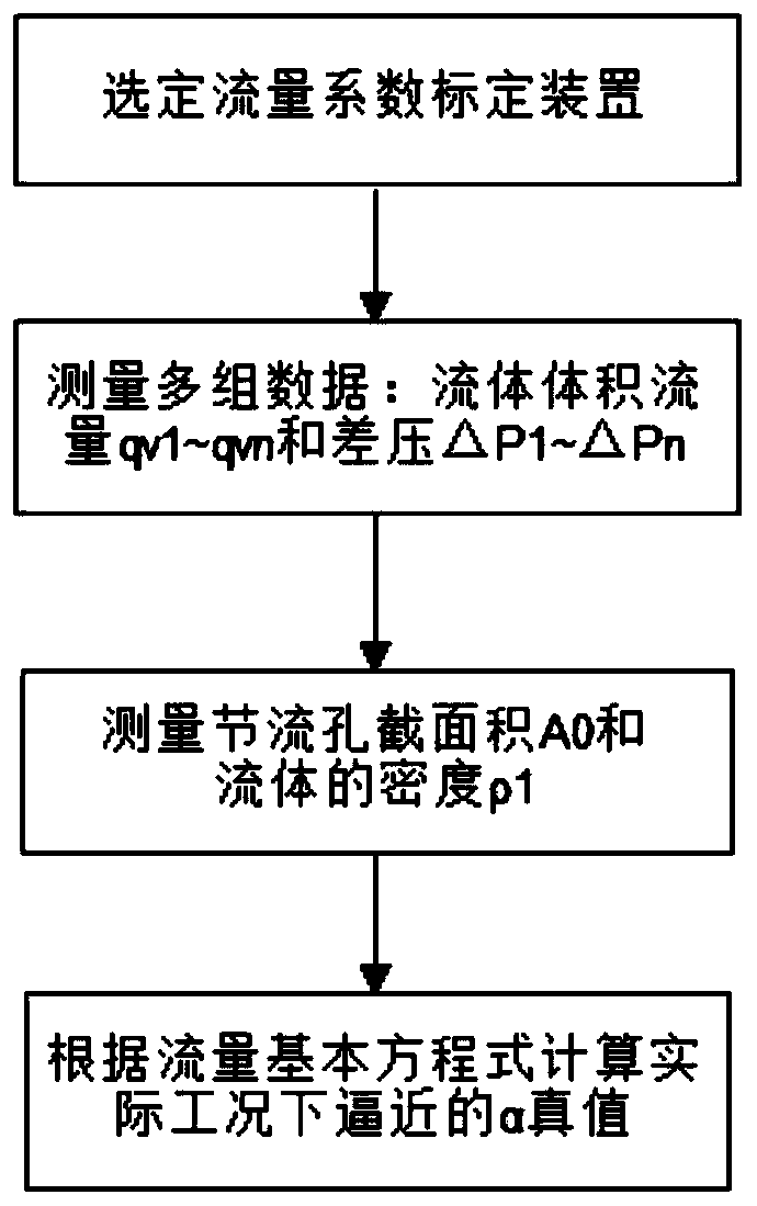
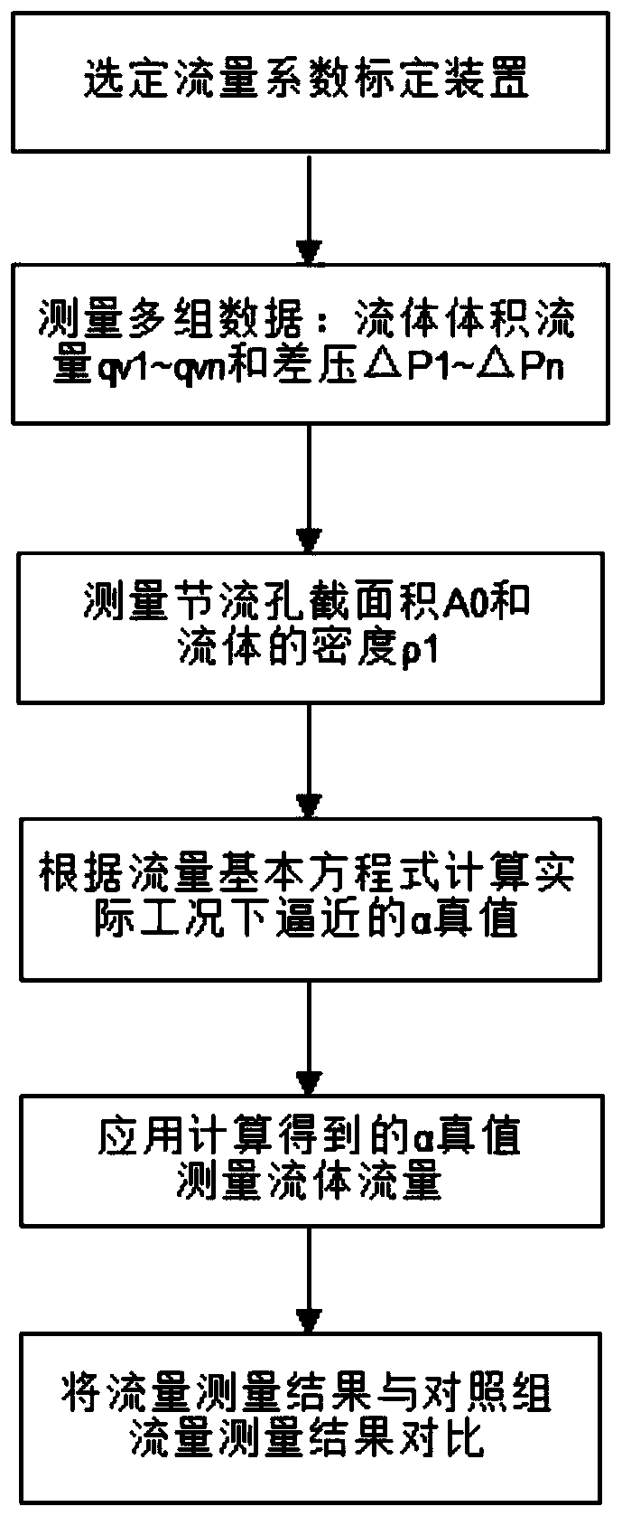
[0057] This embodiment provides a flow coefficient calibration method, such as figure 1 shown, including the following steps:

[0058] S1. Select the standard flow device with the differential pressure flowmeter to be tested as the flow coefficient calibration device;

[0059] S2. Use a standard flow device to measure the flow of the fluid to obtain the first set of data: volume flow q v1 and the differential pressure △P output by the differential pressure flowmeter 1 ;

[0060] S3. Repeat step S2 several times to obtain several sets of data: volume flow q v2 ~q vn and the differential pressure △P output by the differential pressure flowmeter 2 ~△P n ;

[0061] S4. Measure and calculate the cross-sectional area of ​​the orifice of the differential pressure flowmeter, and measure the density of the measured fluid under working conditions;

[0062] S5. Several sets of data measured in steps S2~S3: volume flow q v1 ~q vn , differential pressure △P 1 ~△P n , the data c...

Embodiment 2

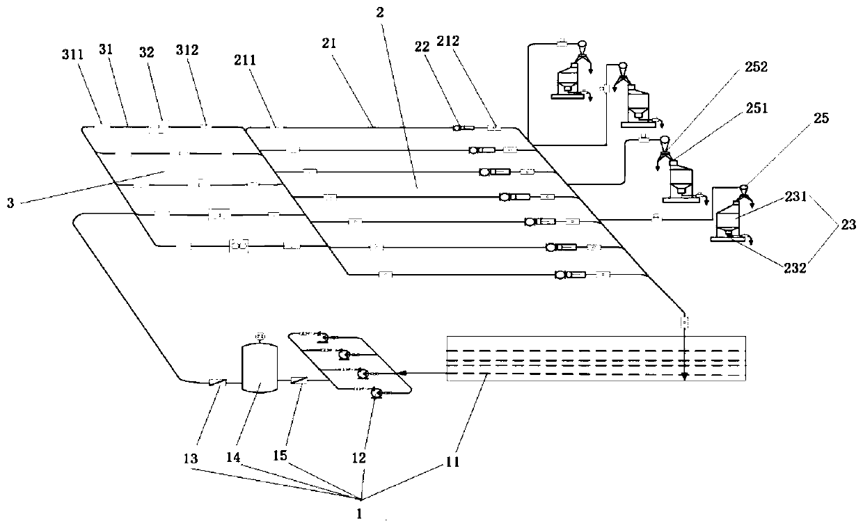
[0078] This embodiment provides a standard flow device, such as image 3 As shown, it includes a fluid supply system 1 , a first verification pipeline group 2 connected to the fluid supply system 1 at one end, and a control system 4 .

[0079] The fluid supply system 1 includes a liquid storage tank 11, a pump 12 arranged on one side of the liquid storage tank 11 for driving fluid flow, and a first switch valve 13 used to control pipeline circulation and cut-off, the first switch valve 13 is located at the pump 12 and the first verification pipeline group 2. A surge tank 14 for increasing the stability of the fluid in the pipeline is provided between the pump 12 and the first switch valve 13 , and a second switch valve 15 is provided between the pump 12 and the surge tank 14 .

[0080] The first test pipeline group 2 includes several first test pipelines 21 connected in parallel with different pipe diameters. A differential pressure flowmeter 22 to be tested is provided on t...


PUM


Abstract

The invention discloses a flow coefficient calibration method. The method comprises the following steps of selecting a flow coefficient calibration device; measuring multiple groups of fluid flows anddifferential pressure data; measuring an orifice cross-sectional area and fluid density; and calculating an approximate alpha true value under an actual operating condition. The invention discloses aflowmeter verification method. The method comprises the following steps of applying calculated alpha true value to measure the fluid flow; and comparing a flow measurement result with a control groupflow measurement result and the like. The invention also discloses a standard flow device. The device comprises a fluid supply system (1) and a first verification pipeline group (2). Or the standardflow device also comprises a second verification pipeline group (3) which is connected in series with the first verification pipeline group (2). In the invention, operation is simple, versatility is high, performance is stable, verification of the plurality of flowmeters can be performed at the same time, and a standard table method and a static mass method are combined to greatly improve verification accuracy.

Description

technical field [0001] The invention relates to the technical field of flowmeter verification, in particular to a flow coefficient calibration, a flowmeter verification method and a standard flow device. Background technique [0002] Flow measuring instruments, pressure measuring instruments, temperature measuring instruments and level measuring instruments are important components of industrial automation instrumentation systems, because the influencing factors of pressure, temperature and level measuring processes are relatively simple, and the development and use of instruments develop rapidly , the country has reached a fairly high level. The flow measurement process itself is affected by many factors (temperature, pressure, density, Reynolds number, expansion coefficient, friction coefficient, pipeline roughness, fluid characteristics, etc.), therefore, the development, production, use, and maintenance of flow measurement products are subject to Theoretical basis (rela...

Claims


Application Information

Patent Timeline
Patent Type & Authority Applications(China)
IPC IPC(8): G01F25/00
Inventor 唐陈一郎禹继波李文亮
Owner 银川融神威自动化仪表厂(有限公司)
Why Eureka
Try Eureka