Wet etching equipment and photoresist cleaning developing device

A wet etching and equipment technology, applied in the field of MEMS, can solve the problems of fracture and breakage of fine structures, and achieve the effects of strong corrosion resistance, easy temperature adjustment, and improved etching uniformity

Active Publication Date: 2019-06-21
SHANGHAI INST OF TECH
View PDF3 Cites 4 Cited by
  • Summary
  • Abstract
  • Description
  • Claims
  • Application Information

AI Technical Summary

Problems solved by technology

[0004] In the existing wet etching, the required etching device is usually soaked in the etching solution. When this process method is used to etch the small-sized (5 micron) complex and precise device structures such as hollows and grids, when it is used When the etching device leaves the etching liquid surface, due to the surface tension of the liquid, the fine structures such as hollows and grids will be broken and broken

Method used


Image

  • Wet etching equipment and photoresist cleaning developing device
  • Wet etching equipment and photoresist cleaning developing device
  • Wet etching equipment and photoresist cleaning developing device

Examples


Embodiment 1

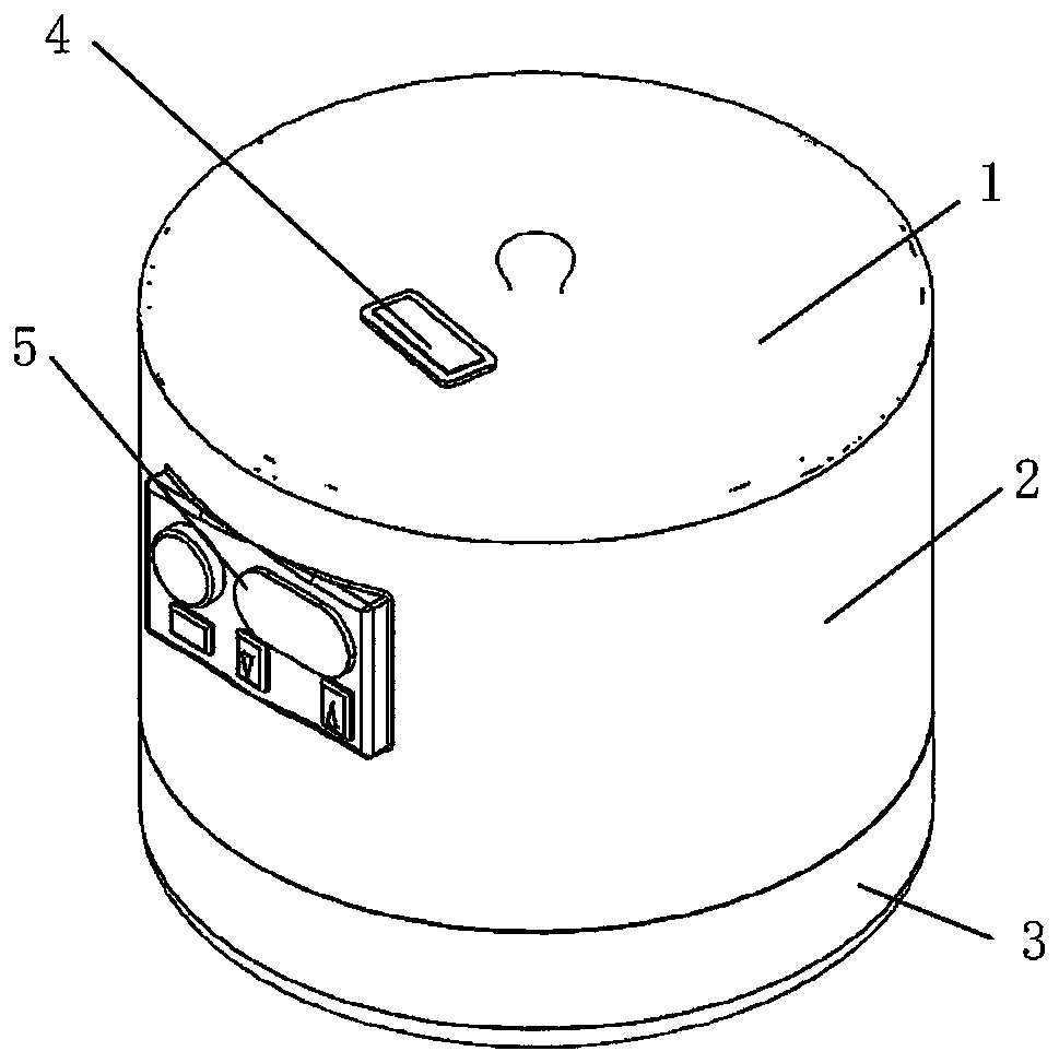
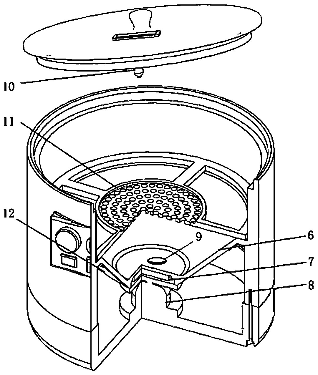
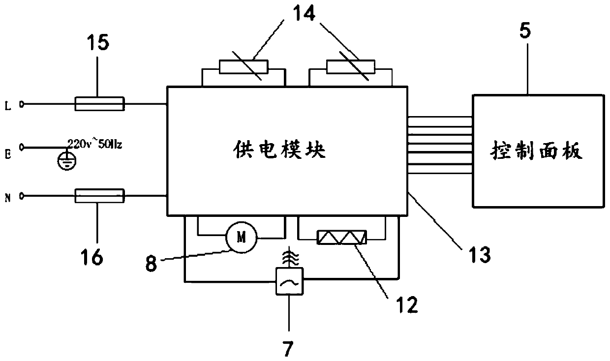
[0038] Such as figure 1 with 2 As shown, the wet etching equipment provided by the present invention includes: a housing, a control panel 5 is arranged on the outer wall of the housing; a liquid carrier basin 6 is arranged in the housing for holding a solution; The edge of the basin is fixedly connected with the inner wall of the housing; the ultrasonic atomizer 7 is fixed on the bottom of the liquid-carrying basin 6, and is used to atomize the solution in the liquid-carrying basin 6 into droplets; the etching flower basket 11 is arranged on the carrying On the basin edge of the liquid basin 6, it is used to hold the etched device; the etched device is separated from the solution; the power supply module 13 is arranged at the bottom of the housing; wherein, the ultrasonic atomizer 7 is electrically connected to the control panel 5 ; The ultrasonic atomizer 7 and the control panel 5 are electrically connected to the power supply module 13 .

[0039] The wet etching equipment ...

Embodiment 2

[0048] The present invention also provides a photoresist cleaning and developing device, including the wet etching equipment in the first embodiment above.

[0049] Specifically, the photoresist cleaning and developing device is used for the development process after traditional photolithography exposure. The photoresist developing solution is poured into the liquid carrier basin 6 and immersed in the device to be developed. If necessary, the electric heating patch can be adjusted. 12 Heating the developing solution without installing the etching flower basket 11 and opening the ultrasonic atomizer 7 .

[0050] The photoresist cleaning and developing device uses the post-exposure drying process. If the photoresist has a small adhesive force to the substrate and the traditional developing method of the photoresist surface has a large internal stress, it is easy to cause the photoresist to fall off and crack when it is etched. As described in Embodiment 1, it is necessary to ins...


PUM


Abstract

The invention discloses wet etching equipment and a photoresist cleaning developing device. The wet etching equipment comprises a shell, a liquid loading basin, an ultrasonic nebulizer, an etching basket, an etched device and a power supply module, wherein a control panel is arranged on an outer wall of the shell, the liquid loading basin is arranged in the shell and is used for loading a solution, a basin edge of the liquid loading basin is fixedly connected with an inner wall of the shell, the ultrasonic nebulizer is fixedly arranged at the bottom of the liquid loading basin and is used foratomizing the solution in the liquid loading basin to liquid drops, the etching basket is arranged at the basin edge of the liquid loading basin and is used for loading the etched device, the etched device is separated from the solution, the power supply module is arranged at the bottom of the shell, the ultrasonic nebulizer is electrically connected with the control panel, and the ultrasonic nebulizer and the control panel both are electrically connected with the power supply module. The etched device is separated from the solution by the etching basket, the etching liquid is atomized by theultrasonic nebulizer, the device is etched by the atomized liquid drops, so that a hollow or lattice fine complicated structure is stably released, and the success rate of etching the fine complicatedstructure is provided.

Description

technical field [0001] The invention belongs to the technical field of MEMS (micro-electromechanical systems), and in particular relates to a wet etching device and a photoresist cleaning and developing device. Background technique [0002] Photolithography is an important step in the manufacturing process of semiconductor devices. This step uses exposure and development to describe the geometric pattern structure on the photoresist layer, and then transfers the pattern on the photomask to the substrate by etching. [0003] Etching is most commonly divided into: dry etching and wet etching. Wet etching is a purely chemical reaction process, which refers to using the chemical reaction between the solution and the pre-etching material to remove the part not masked by the masking film material to achieve the purpose of etching. [0004] However, the existing wet etching usually puts the required etching device into the etching solution and soaks it. When this process method is...

Claims


Application Information

Patent Timeline
Patent Type & Authority Applications(China)
IPC IPC(8): H01L21/67G03F7/30
Inventor 李以贵蔡金东王欢张成功吴文渊王洁金敏慧
Owner SHANGHAI INST OF TECH
Why Eureka
Try Eureka