Field sequential image display device and image display method
An image display device and field sequence technology, applied to static indicators, nonlinear optics, instruments, etc., can solve the problems of insufficient distribution ratio and unreliable suppression of color chaos, so as to suppress color chaos, improve color reproducibility, The effect of cutting calories
- Summary
- Abstract
- Description
- Claims
- Application Information
AI Technical Summary
Problems solved by technology
Method used
Image
Examples
no. 1 approach >
[0123]
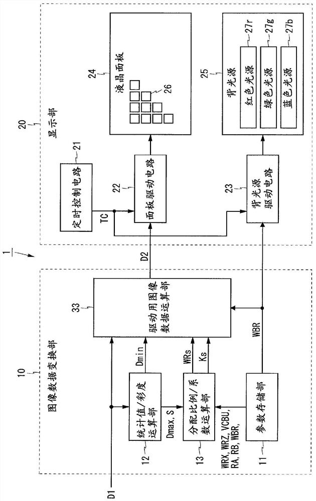
[0124] figure 1 It is a block diagram showing the configuration of the image display device of the first embodiment. figure 1 The illustrated image display device 1 includes an image data conversion unit 10 and a display unit 20 . The image data conversion unit 10 includes a parameter storage unit 11 , a statistical value / saturation calculation unit 12 , a distribution ratio / coefficient calculation unit 13 , and a driving image data calculation unit 33 . The display unit 20 includes a timing control circuit 21 , a panel drive circuit 22 , a backlight drive circuit 23 , a liquid crystal panel 24 as a light modulation unit, and a backlight 25 as a light source unit.
[0125] The image display device 1 is a field sequential liquid crystal display device. The image display device 1 divides one frame period into a plurality of subframe periods, and displays subframes of different colors in each subframe period. The following image display device 1 is configured to d...
no. 2 approach >
[0251]
[0252] Figure 14 It is a block diagram showing the configuration of the image display device of the second embodiment. Figure 14 The illustrated image display device 3 includes an image data conversion unit 30 and a display unit 40 . In the image data conversion unit 30 of the first embodiment, the distribution ratio / coefficient calculation unit 13 is replaced by the distribution ratio / coefficient calculation unit 32 , and the parameter storage unit 11 is replaced by the parameter storage unit 31 . Differences from the first embodiment will be described below.
[0253] The image display device of the present embodiment selectively performs low-brightness part noise countermeasure processing, and further selectively performs high-brightness part noise countermeasure processing. In the image display device of the present embodiment, the parameter storage unit 31 stores not only parameters WRX, RA, RB, and WBR but also parameters NR, GL, RC, WRY, WRZ0, and WRZ1. T...
no. 3 approach >
[0337] Figure 26 It is a block diagram showing the configuration of the image display device of the third embodiment. Figure 26 The illustrated image display device 5 includes an image data conversion unit 50 and a display unit 60 . The image data conversion unit 50 is configured by adding a parameter selection unit 52 to the image data conversion unit 30 of the second embodiment, and replacing the parameter storage unit 31 with the parameter storage unit 51 . The display unit 60 is configured by adding the temperature sensor 61 to the display unit 40 of the second embodiment. Differences from the first embodiment will be described below.
[0338] The temperature sensor 61 is included in the display unit 60 and measures the temperature T of the display unit 60 . The temperature sensor 61 is provided near the liquid crystal panel 24, for example. The temperature T measured by the temperature sensor 61 is input to the parameter selection unit 52 .
[0339] The parameter s...
PUM
 Abstract
Description
Claims
Application Information
 - R&D
- Intellectual Property
- Life Sciences
- Materials
- Tech Scout
- Unparalleled Data Quality
- Higher Quality Content
- 60% Fewer Hallucinations
Browse by: Latest US Patents, China's latest patents, Technical Efficacy Thesaurus, Application Domain, Technology Topic, Popular Technical Reports.
© 2025 PatSnap. All rights reserved.Legal|Privacy policy|Modern Slavery Act Transparency Statement|Sitemap|About US| Contact US: help@patsnap.com


