
Powder spraying process and device of heat preservation cover

A technology of thermal insulation cover and powder spraying, which is applied in the direction of paint spraying room, spraying device, and device for coating liquid on the surface, etc., can solve the problems of powder falling and air bubbles from the thermal insulation cover, affecting the thermal insulation cover, powder flowing, etc., so as to reduce the cleaning cost. , Improve the cleaning effect, improve the quality of the effect

Active Publication Date: 2019-06-25
浙江东蓝机电有限公司
View PDF7 Cites 7 Cited by
  • Summary
  • Abstract
  • Description
  • Claims
  • Application Information

AI Technical Summary

Problems solved by technology

[0006] In the existing powder spraying and curing process, the process of cleaning the heat preservation cover is generally lacking, which is easy to affect the powder spraying and curing quality of the heat preservation cover due to the adhesion of impurities, and the heat preservation cover is prone to powder drop and air bubbles. In addition, the application of the above two utility models can It can be seen that 1. When the heat preservation cover is spraying powder, it is easy to cause incomplete powder spraying due to the shelter of the hanger. 2. The air duct directly sends the wind into the curing drying tunnel. Because the powder that needs to be solidified is hit by the airflow generated by the wind, it will Make the powder flow, easy to affect the curing quality

Method used


Image

  • Powder spraying process and device of heat preservation cover
  • Powder spraying process and device of heat preservation cover
  • Powder spraying process and device of heat preservation cover

Examples


Embodiment Construction

[0036] The following will clearly and completely describe the technical solutions in the embodiments of the present invention with reference to the accompanying drawings in the embodiments of the present invention. Obviously, the described embodiments are only some, not all, embodiments of the present invention. Based on the embodiments of the present invention, all other embodiments obtained by persons of ordinary skill in the art without making creative efforts belong to the protection scope of the present invention.

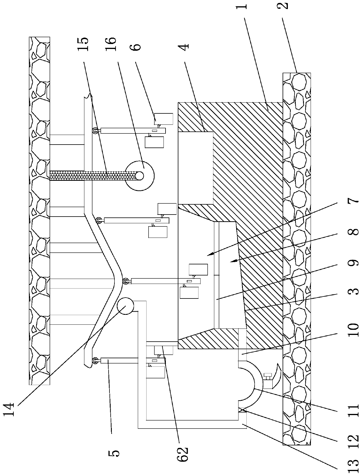
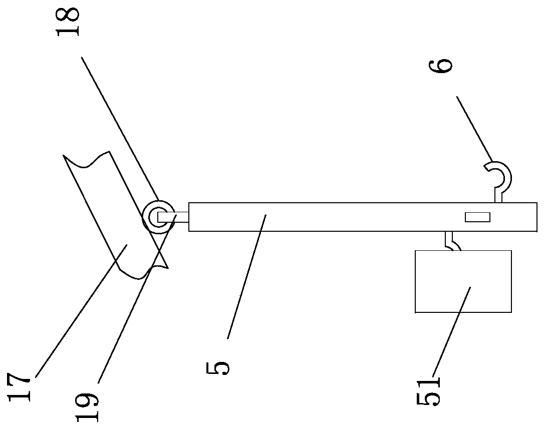
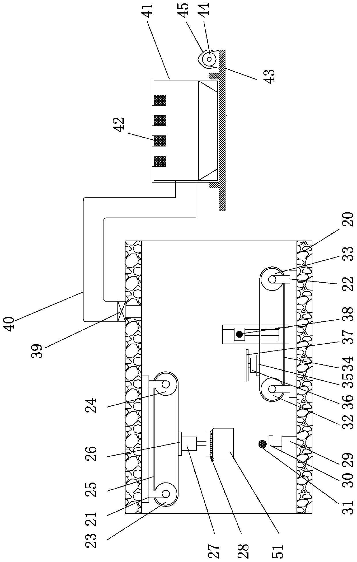
[0037] Such as Figure 1-8 As shown, the powder spraying equipment of this thermal insulation cover 51 comprises cleaning machine, powder spraying device and curing device, and cleaning machine comprises body 1 and frame 2, and body 1 is installed on frame 2, has cleaning tank 3 in body 1 And the effusion tank 4, the frame 2 is provided with a conveying mechanism, the lower end of the conveying mechanism has several straight rods 5 arranged downwards, and the ...


PUM


Abstract

The invention provides a powder spraying process and equipment of a heat preservation cover, and belongs to the technical field of machining. The powder spraying equipment of the heat preservation cover comprises a cleaning machine, a powder spraying device and a curing device, the cleaning machine comprises a machine body and a rack, the machine body is arranged on the rack, the machine body is internally provided with a cleaning groove and a liquid accumulation groove, a conveying mechanism is arranged on the rack, the powder spraying device comprises a case, an upper conveying structure anda lower conveying structure are arranged in the case, the heat preservation cover sequentially passes through the upper conveying structure and the lower conveying structure, a first powder sprayingmechanism is arranged on the lower end of the upper conveying structure, at least one set of opposite second powder spraying mechanisms are arranged on the two sides of the lower conveying structure,the case further communicates with a powder recycling device, the upper conveying structure is arranged on the top in the case through an upper support, the lower conveying structure is arranged on the bottom in the case through a lower support, the curing device comprises a curing box, and a preheating cavity, a curing cavity and a cooling cavity are formed in the curing box. The heat preservation cover can be kept clean and is subjected to non-dead-corner powder spraying, and in addition, during curing, powder falling is not prone to happening.

Description

technical field [0001] The invention belongs to the technical field of machinery, and relates to a powder spraying process of a heat preservation cover and equipment thereof. Background technique [0002] Pressure cooker is also called pressure cooker, pressure cooker, is a kind of kitchen utensils. The pressure cooker uses the physical phenomenon that the boiling point of the liquid will increase at a higher pressure, and puts pressure on the water so that the water can reach a higher temperature without boiling, so as to speed up the efficiency of stewing food. It can be used to heat the cooked food to above 100°C. In high altitude areas, the pressure cooker can avoid the problem that the boiling point of water is lowered and the food is not easy to cook. [0003] The heat preservation cover is an important part of the pressure cooker. There is a powder spraying process in the production process of the heat preservation cover. After the powder spraying, the heat preservat...

Claims


Application Information

Patent Timeline
Patent Type & Authority Applications(China)
IPC IPC(8): B05B16/20B05B13/06B05B13/02B05B13/04B05B14/10B05D3/00B05D3/04B05D1/12B08B9/00
CPCY02P70/10
Inventor 巫朝常余志荣卢政良吴天一
Owner 浙江东蓝机电有限公司
Learn More