Part cutting equipment for die machining

A cutting equipment and mold processing technology, applied in metal processing and other directions, can solve problems affecting cutting effect and product quality, mold cutting deviation, part offset, etc.

Inactive Publication Date: 2019-06-25
YUNXIAN LIDA COMML VEHICLE COMPLETE CO LTD
View PDF0 Cites 7 Cited by
  • Summary
  • Abstract
  • Description
  • Claims
  • Application Information

AI Technical Summary

Problems solved by technology

[0004] In the mold processing process, the cutting of the mold is a regular work. In the mold cutting process, the part deviation often occurs because the mold is not fixed tightly, resulting in deviation of the mold cutting, which affects the cutting effect and product quality.

Method used


Image

  • Part cutting equipment for die machining
  • Part cutting equipment for die machining
  • Part cutting equipment for die machining

Examples


Embodiment Construction

[0016] The following will clearly and completely describe the technical solutions in the embodiments of the present invention with reference to the accompanying drawings in the embodiments of the present invention. Obviously, the described embodiments are only some, not all, embodiments of the present invention. Based on the embodiments of the present invention, all other embodiments obtained by persons of ordinary skill in the art without making creative efforts belong to the protection scope of the present invention.

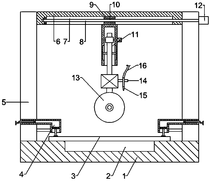
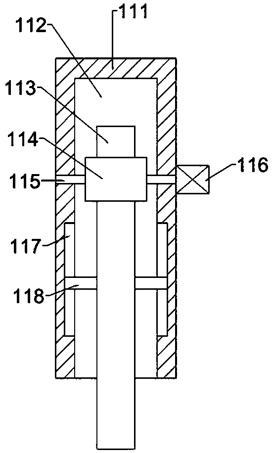
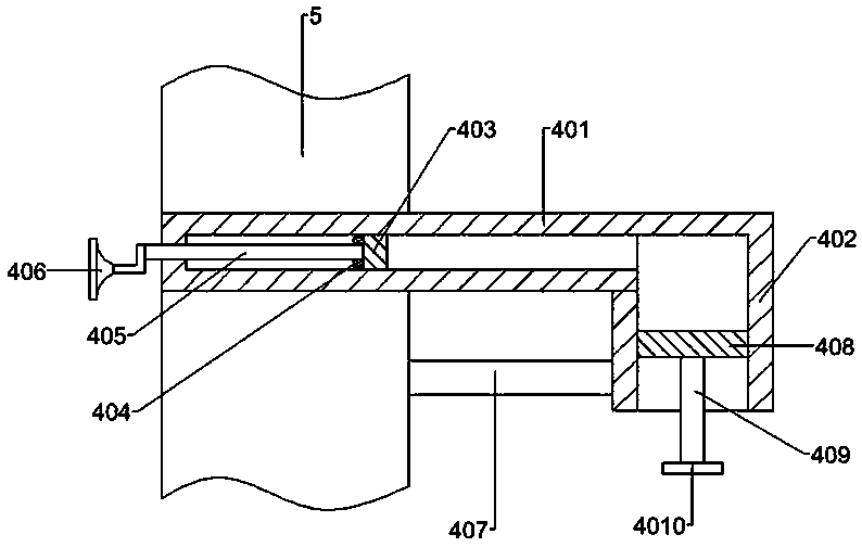
[0017] see Figure 1-Figure 3 , in an embodiment of the present invention, a part cutting device for mold processing includes a base 1, a support frame 5 is fixedly connected to both sides of the base 1, a top plate 6 is fixedly connected to the top of the support frame 5, and a top plate 6 is set on the top plate 6. There is a moving groove 7 with the opening facing downwards, a moving block 9 is arranged in the moving groove 7, a horizontal threaded through ...


PUM


Abstract

The invention relates to part cutting equipment for die machining. The part cutting equipment for die machining comprises a base, wherein two sides of the base are fixedly connected with a supportingframe, the top end of the supporting frame is fixedly connected with a top plate, a moving groove with a downward opening is formed in the top plate, a moving block is arranged in the moving groove, ahorizontal threaded through hole is formed in the moving block, a first threaded rod is in threaded connection with the horizontal threaded through hole, the first threaded rod is erected at two endsof the moving groove, and the right end of the first threaded rod is fixedly connected with an output shaft of a first motor; and the lower side of the moving block is fixedly connected with a lifting device, the lower side of the lifting device is fixedly connected with a cutting device, and the lifting device comprises an installation column. The part cutting equipment for die machining has thebeneficial effects that a second moving plate moves downwards under the action of hydraulic oil to drive a pressure plate to extrude a die, and the fixing effect of the die is effectively realized; and a second motor drives a rotating shaft to rotate, the rotating shaft drives a gear to rotate, and a rack meshing with the gear moves downwards, so that the cutting device is driven to move downwards.

Description

technical field [0001] The invention relates to the technical field of mold processing, in particular to a part cutting device for mold processing. Background technique [0002] Mold (mú jù), various molds and tools used in industrial production for injection molding, blow molding, extrusion, die-casting or forging forming, smelting, stamping and other methods to obtain the required products. In short, a mold is a tool used to make shaped objects. This tool is composed of various parts, and different molds are composed of different parts. It mainly realizes the processing of the shape of the article through the change of the physical state of the formed material. Known as the "Mother of Industry". [0003] Under the action of external force, the blank becomes a tool with a specific shape and size. Widely used in blanking, die forging, cold heading, extrusion, powder metallurgy parts pressing, pressure casting, and compression molding or injection molding of engineering pl...

Claims


Application Information

Patent Timeline
Patent Type & Authority Applications(China)
IPC IPC(8): B26D7/02B26D1/04B26D5/08B26D7/08
Inventor 曾明宗曾明典胡君曾跃文
Owner YUNXIAN LIDA COMML VEHICLE COMPLETE CO LTD
Why Eureka
Try Eureka