Eureka AIR delivers breakthrough ideas for toughest innovation challenges, trusted by R&D personnel around the world.

Cooking method of automatic cooking utensil

A cooking method and automatic cooking technology, which is applied to cooking utensils, household utensils, kitchen utensils, etc., can solve the problems of uneven heating and mixing of ingredients, bad taste, etc., and achieve the effect of increasing the probability of heating, avoiding the stickiness of ingredients, and promoting heating

Active Publication Date: 2019-07-02
JOYOUNG CO LTD
View PDF10 Cites 2 Cited by
  • Summary
  • Abstract
  • Description
  • Claims
  • Application Information

AI Technical Summary

Problems solved by technology

[0005] The purpose of the present invention is to provide a cooking method for automatic cooking utensils, which can solve the problem of bad taste caused by uneven heating and mixing of ingredients in the prior art

Method used


Image

  • Cooking method of automatic cooking utensil
  • Cooking method of automatic cooking utensil
  • Cooking method of automatic cooking utensil

Examples


Embodiment 1

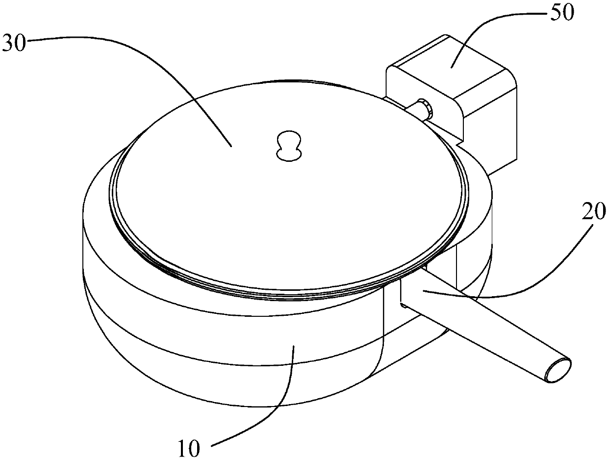
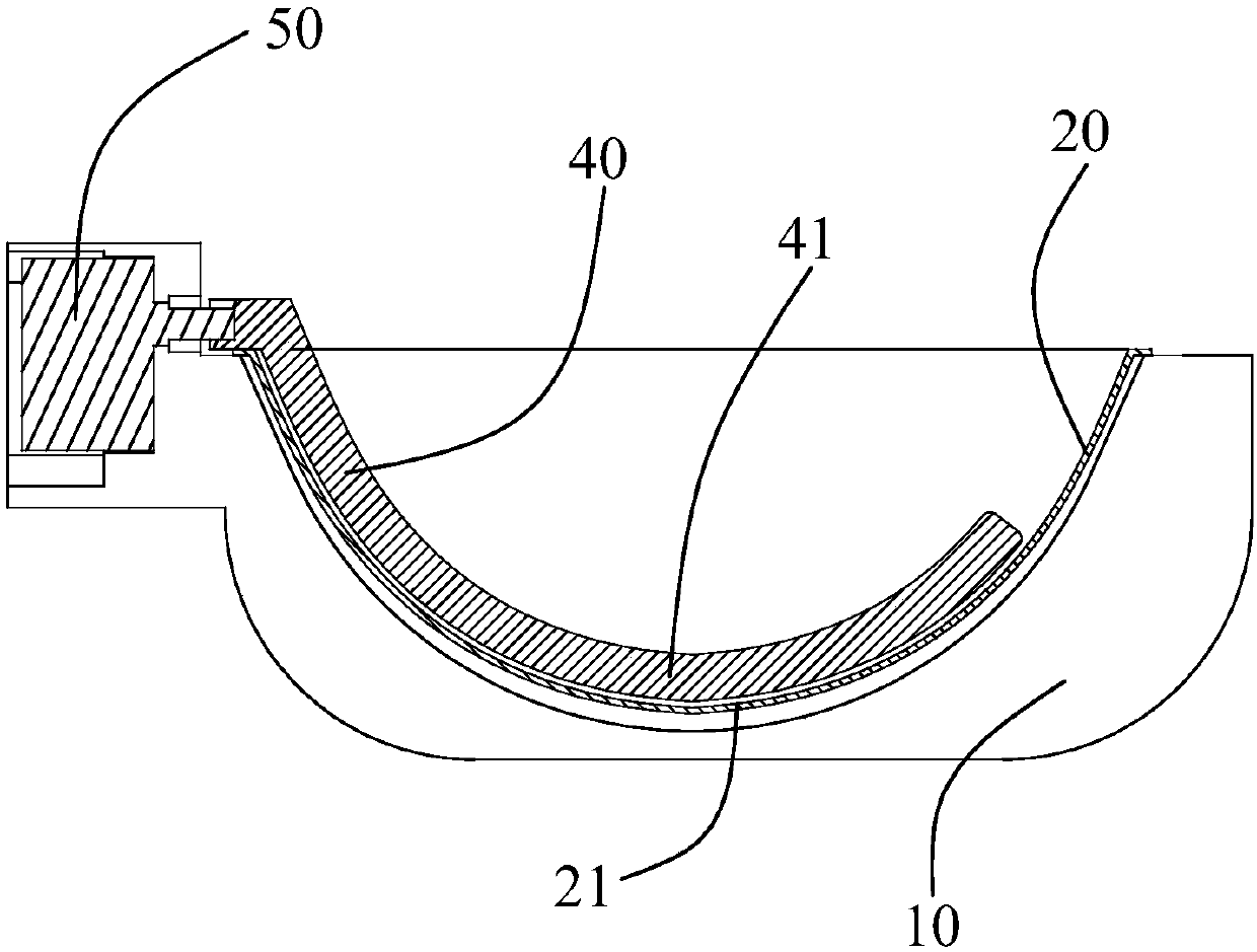
[0033] combine Figures 1 to 4 As shown, in the embodiment of the present invention, the automatic cooking appliance includes a machine base 10, a pot body 20, a pot cover 30, a stirring paddle 40, and a driving device 50 for driving the stirring paddle 40, and the pot body 20 is a rotating Body, the pot body 20 is embedded into the machine base 10, the pot cover 30 is fastened on the pot body 20, the stirring paddle 40 is arranged in the pot body 20 in a laterally swingable manner, and the swing center axis of the stirring paddle 40 is in line with the The central axis of rotation of the pot body 20 is vertical. The cooking utensil also includes a heating device 60 , which may be electromagnetic heating or electric heating tube heating. The shape of the heating device 60 is adapted to the outer wall of the pot body 20 . It can be understood that the stirring paddle 40 can be fixed on the pot cover 30, and when the pot cover 30 is fastened on the pot body 20, the stirring pad...

Embodiment 2

[0068] Different from Embodiment 1, in this embodiment, if Figure 8 As shown, the heating device forms a first heating area S on the pot body. In the preheating stage, the stirring paddle 40 swings at a first deviation angle to make the material deviate from the first heating area, and in the first deviation The angle stops the first time. It can be understood that the first heating area on the pot body is an area corresponding to the shape of the heating device.

[0069] In this way, at least most of the ingredients can be moved to a side other than the first heating area of ​​the pot body 20 by the stirring paddle 40, so that the ingredients and the seasoning are separated. During the stirring process and the process of continuing at this angle, cooking oil and The liquid seasoning can flow back to the central area of ​​the bottom of the pot body 20 through the gap between the stirring paddle 40 and the pot body 20, so that the heat at the bottom of the pot body can be tra...


PUM


Abstract

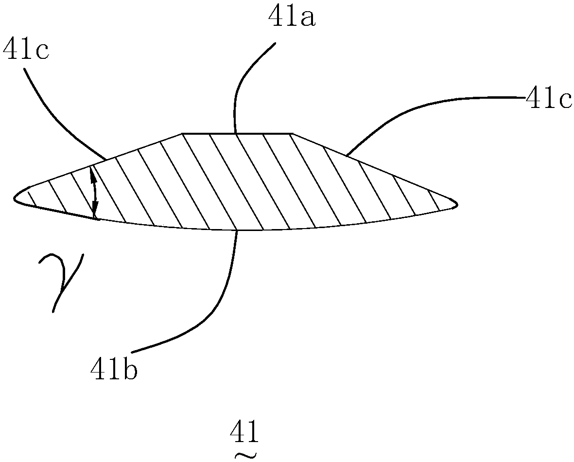
The invention relates to a cooking method of an automatic cooking utensil. The cooking utensil comprises a pot, a transversely-arranged stirring blade, a heating device and a driving device, wherein the driving device drives the stirring blade to swing in the pot for stirring, the stirring blade at least comprises an arc segment in a length direction, and a cambered surface matched with the arc segment is arranged on an inner wall of the pot. The method at least comprises a first stir-fry stage, and in the stage, the stirring blade swings at first speed to make a material tossed on the inner wall of the pot and the cambered surface area matched with the arc segment, wherein a derivation angle of swing is larger than an included angle between the bottom surface and a side surface of the arcsegment. According to the scheme, by adopting the cooking method of the automatic cooking utensil, in a reciprocating swing process of the stirring blade, the material can be made to conduct obliqueprojectile motion or horizontal projectile motion towards a central side of the pot, and is tossed into the inner wall of the pot and the cambered surface area matched with the arc segment, so that finally, a pot tossing effect of a manual cooking process is simulated, evener heating of the food material is promoted, and the taste of the food material is improved.

Description

technical field [0001] The invention relates to the field of household appliances, in particular to a cooking method for an automatic cooking appliance. Background technique [0002] With the quickening pace of life, more and more people begin to need equipment capable of automatic cooking. Therefore, cooking machines with functions such as automatic heating of oil, automatic stir-frying, and automatic temperature control have appeared. This type of cooking machine usually includes Machine base, pot body, stirring paddle and pot cover, etc., wherein the stirring paddle is vertically installed on the pot cover, and the stirring paddle is driven to rotate by the driving motor, thereby driving the movement of the ingredients in the pot to achieve stir frying. [0003] However, this type of cooking machine only rotates and stirs during the stirring process, and the ingredients are only pushed by the horizontal direction of the stirring paddle, so that the ingredients just rotate...

Claims


Application Information

Patent Timeline
Patent Type & Authority Applications(China)
IPC IPC(8): A47J36/16
CPCA47J36/165
Inventor 朱泽春刘孝碧杨杰钱海针
Owner JOYOUNG CO LTD
Why Eureka
Eureka Blog
Learn More