
Gear forging waste recycling and re-machining device

A technology for scrap recycling and gear forging, applied in the field of mechanical processing and forging, can solve the problems of wasting raw materials, elongated processing time, uneven metal distribution, etc., and achieves the effect of saving processing costs, avoiding waste of resources, and uniform radial distribution.

Active Publication Date: 2019-07-05
CHANGZHOU AILUN MACHINERY
View PDF27 Cites 0 Cited by
  • Summary
  • Abstract
  • Description
  • Claims
  • Application Information

AI Technical Summary

Problems solved by technology

However, due to the high hardness of the gear forging material, horseshoe-shaped deformation may occur during shearing, and the metal is unevenly distributed along the radial direction of the blank, resulting in an increase in the wall thickness difference during subsequent extrusion molding, so that the formed parts are scrapped and the production cost increases sharply.
However, it is difficult to accurately measure the size of the blank by general forging shearing, and manual shearing is time-consuming and laborious, which greatly affects the subsequent processing progress.
The existing forging processing equipment has successively improved the shearing process in the early stage of forging, so that the shape of the blank material after shearing is more in line with the forging requirements. However, precise cutting not only prolongs the processing time, but also has higher requirements for the quality of the cut parts. The price is expensive and does not meet the current market demand for forging processing
And the remaining waste after cutting needs to be processed separately, which not only wastes raw materials but also consumes redundant manpower and material resources.

Method used


Image

  • Gear forging waste recycling and re-machining device
  • Gear forging waste recycling and re-machining device
  • Gear forging waste recycling and re-machining device

Examples


Embodiment Construction

[0014] The following will clearly and completely describe the technical solutions in the embodiments of the present invention with reference to the accompanying drawings in the embodiments of the present invention. Obviously, the described embodiments are only some, not all, embodiments of the present invention. Based on the embodiments of the present invention, all other embodiments obtained by persons of ordinary skill in the art without making creative efforts belong to the protection scope of the present invention.

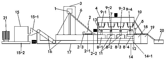
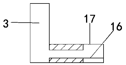
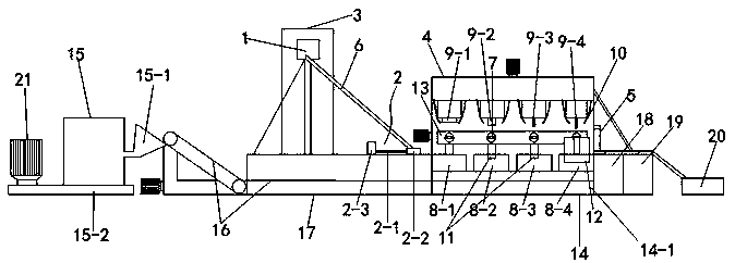
[0015] according to Figure 1-2 , a gear forging waste recycling and reprocessing device, including an automatic feeding device 1, an automatic transmission device 2, a heating and sorting device 3, a device main body 4, a discharge port 5 and a slide rail 6; the automatic feeding device 1 is connected to The heating and sorting device 3, the position of the heating and sorting device 3 is higher than the automatic transmission device 2, and the device main bo...


PUM


Abstract

The invention discloses a gear forging waste recycling and re-machining device. An automatic feeding device and an automatic transmission device are included. The automatic feeding device is connectedwith a heating sorting device. The position of the heating sorting device is higher than the automatic transmission device, and the heating sorting device is connected with a body part of the whole device through a sliding rail. The end, away from the sliding rail, of the body part of the device is connected with a discharging port, and a conveying belt is arranged between the discharging port and the body part of the device. The body part comprises automatic clamping mechanical arms, a workbench set, an automatic forming device and a cooling device. The gear forging waste recycling and re-machining device effectively avoids the phenomena that during gear forging material shearing, horseshoe shape deformation is possibly generated, metal is unevenly distributed in the radial direction ofblanks, consequently, the wall thickness difference is increased during subsequent extrusion forming, and formed components are scraped; and waste obtained after machining can be reasonably utilized.

Description

technical field [0001] The invention relates to a processing device, which belongs to the field of mechanical processing and forging, in particular to a device for recycling and reprocessing gear forging waste. Background technique [0002] Generally, when the billet is processed and forged, the billet will be forged and heated first, so that the subsequent steps of cutting and forming the billet can be carried out. However, due to the high hardness of the gear forging material, horseshoe-shaped deformation may occur during shearing, and the metal is unevenly distributed along the radial direction of the blank, resulting in an increase in the wall thickness difference during subsequent extrusion molding, so that the formed parts are scrapped and the production cost increases sharply. . However, it is difficult to accurately measure the size of the blank by general forging shearing, and manual shearing is time-consuming and laborious, which greatly affects the subsequent pro...

Claims


Application Information

Patent Timeline
Patent Type & Authority Applications(China)
IPC IPC(8): B21K1/30B02C21/00B02C23/08B22F9/04
CPCB21K1/30B02C21/00B02C23/08B22F9/04B02C2201/06
Inventor 潘翼飞
Owner CHANGZHOU AILUN MACHINERY
Learn More