Active resonance c-type buoyancy pendulum wave energy generation device

A power generation device and wave energy technology, which is applied in ocean energy power generation, engine control, engine components, etc., can solve the problems of reducing the working stroke of the wave force on the wave energy system, increasing the distance, and adversely absorbing waves, and achieving excellent radiation. Hydrodynamic properties, high-efficiency wave energy capture, and the effect of reducing radiant energy

Active Publication Date: 2020-07-10
WUHAN UNIV
View PDF6 Cites 3 Cited by
  • Summary
  • Abstract
  • Description
  • Claims
  • Application Information

AI Technical Summary

Problems solved by technology

However, further research is needed on the wave-facing surface of the eagle-type device. The increase of the distance between the normal direction of the wave-facing surface and the hinge axis will increase the radiation moment on the wave-facing surface, which is not conducive to absorbing waves. It is also not conducive to energy absorption of the device. Similarly, waves will break on the water surface, increasing viscous damping, which is not conducive to wave absorption.
[0006] From the above analysis, it can be seen that the existing wave energy utilization device has: the natural vibration period of the wave energy system brought about by the excessively large attached mass of the device is much higher than the actual wave period, so it is difficult to resonate. On the other hand, the attached damping is too large , making the pendulum amplitude smaller, reducing the stroke of wave force acting on the wave energy system, thereby reducing the input of wave energy to the wave energy system

Method used


Image

  • Active resonance c-type buoyancy pendulum wave energy generation device
  • Active resonance c-type buoyancy pendulum wave energy generation device
  • Active resonance c-type buoyancy pendulum wave energy generation device

Examples


Embodiment Construction

[0052] The present invention will be further described in detail below in conjunction with the attached drawings of the present invention, so that those skilled in the art can understand the solution of the present invention more clearly. However, it does not limit the protection scope of the present invention, and various changes made to the present invention belong to the scope defined by the appended claims.

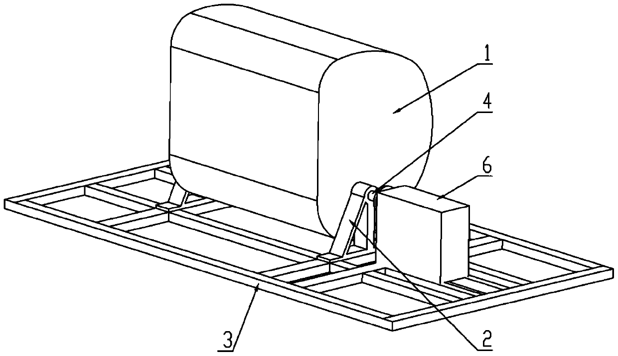
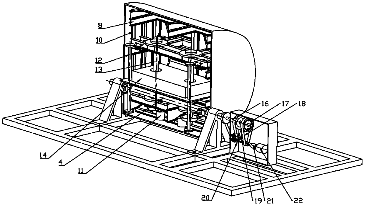
[0053] See attached figure 1 , attached figure 2 As shown, the active resonance C-type buoyancy pendulum wave energy generating device of the present invention includes: an energy capture system, a power generation system 6, and a raft base 3, and the power generation system 6 and the energy capture system are installed on the raft base; The system is used to capture wave energy, convert it into mechanical energy, and transmit it to the power generation system through the main shaft for power generation. The energy harvesting system includes: a pendulum body 1, the...


PUM


Abstract

The invention discloses an active resonance C-type buoyancy pendulum wave energy power generation device, which is a cabin-shaped wave energy power generation device completely submerged in water, including an energy capture system, a power generation system and a raft base. Cabin-shaped pendulum body, with an automatic center-of-mass adjustment device installed in the pendulum body, the pendulum body is fixedly connected to the main shaft, the main shaft is connected to the power generation system, and a code disc for testing the swing of the pendulum body is also set on the main shaft, the two sides of the pendulum body are parallel, and the back wave surface is Two concentric circular arcs with a large top and a small bottom. The transition between the two arcs is a helix, an involute or a high-order curve. The distance between the outer normal on the transition curve and the axis of the main axis is the smallest; the wave front is flat or concave. The arc surface or the same curved surface as the back wave surface; the power generation system includes chains, ratchets, reversing shafts, speed increasers, permanent magnet generators, and the power generation system is built in the pendulum cabin or located outside the pendulum. By adjusting the position of the center of mass of the device, the pendulum body can resonate with the wave in real time to realize efficient conversion of wave energy.

Description

technical field [0001] The invention relates to an active resonance C-type buoyancy pendulum wave energy power generation device, in particular to a power generation device using sea wave energy, which belongs to the technical field of new energy. Background technique [0002] Wave energy is one of the main forms of ocean energy. It is a clean and renewable energy that is easy to use, has a large reserve, is widely distributed, and has a high energy flow density. Among them, the utilization of wave energy is a research hotspot in the world today. Ocean powers around the world are conducting research in this area, and more than 4,500 technical solutions have been proposed. According to the 2016 JRC Ocean Energy Status Report, Attenuator / Point absorber / OWC / OWSC four types of devices The technology maturity level TRL has reached level 8, which is close to commercialization. The technical maturity of the current research mainly reflects the deployment, operation and maintenance...

Claims


Application Information

Patent Timeline
Patent Type & Authority Patents(China)
IPC IPC(8): F03B13/18
CPCF03B13/182F05B2220/7068Y02E10/30F05B2270/202F05B2250/72F05B2250/44F03B13/1825
Inventor 蔡元奇霍银泉刘健慧石祥宇刘洋
Owner WUHAN UNIV
Why Eureka
Try Eureka