Combined condensate liquid pump

A condensate and composite technology, applied in the direction of non-variable pumps, pumps, pump control, etc., can solve the problems of condensate pump cooling capacity to be improved, time-consuming, laborious, mechanical corrosion, etc., to achieve easy balance of local air pressure, condensation process Smooth and reduce the effect of water velocity difference

Inactive Publication Date: 2019-07-05
SHAANXI UNIV OF SCI & TECH
View PDF8 Cites 0 Cited by
  • Summary
  • Abstract
  • Description
  • Claims
  • Application Information

AI Technical Summary

Problems solved by technology

[0003] For existing condensate pumps, the concentricity of the pump shaft and the motor shaft must be guaranteed, and the deviation of the outer circle of the coupling must be within a certain range. Therefore, the foundation plane for installing the pump needs to be leveled with a spirit level. After the foundation cement solidifies, install the pump on the After laying the foundation, you need to use a level to correct the base, etc. The installation process is time-consuming and laborious
In order to reduce the liquid resistance during rotation, the current condensate pump usually designs the impeller to be relatively thin, even with edges. This structure is prone to low-pressure environment, cavitation, mechanical corrosion, and significantly reduced efficiency. , the cooling capacity of the condensate pump needs to be improved

Method used


Image

  • Combined condensate liquid pump
  • Combined condensate liquid pump
  • Combined condensate liquid pump

Examples


Embodiment Construction

[0025] The present invention will be described in further detail below in conjunction with specific examples, but not as a limitation of the present invention.

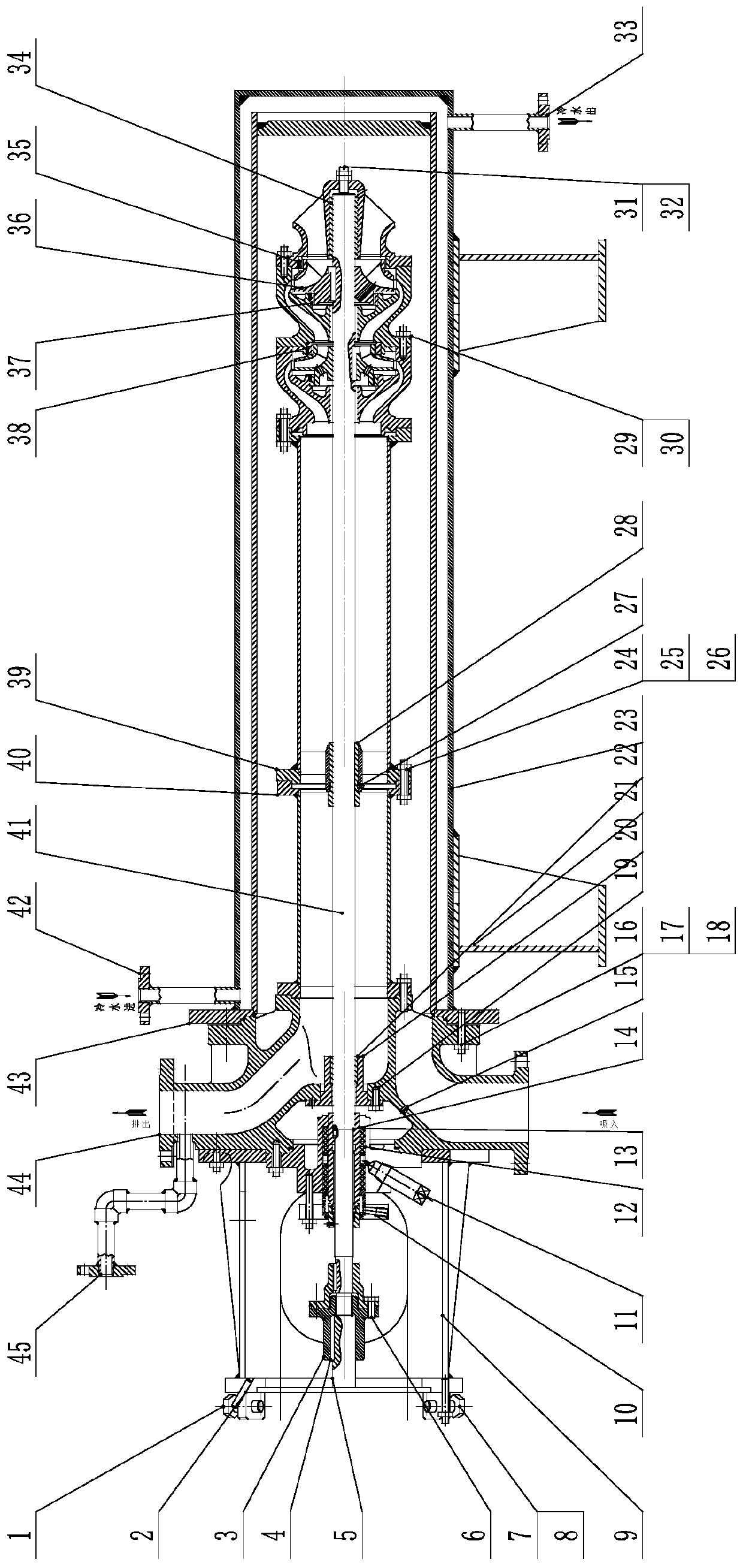
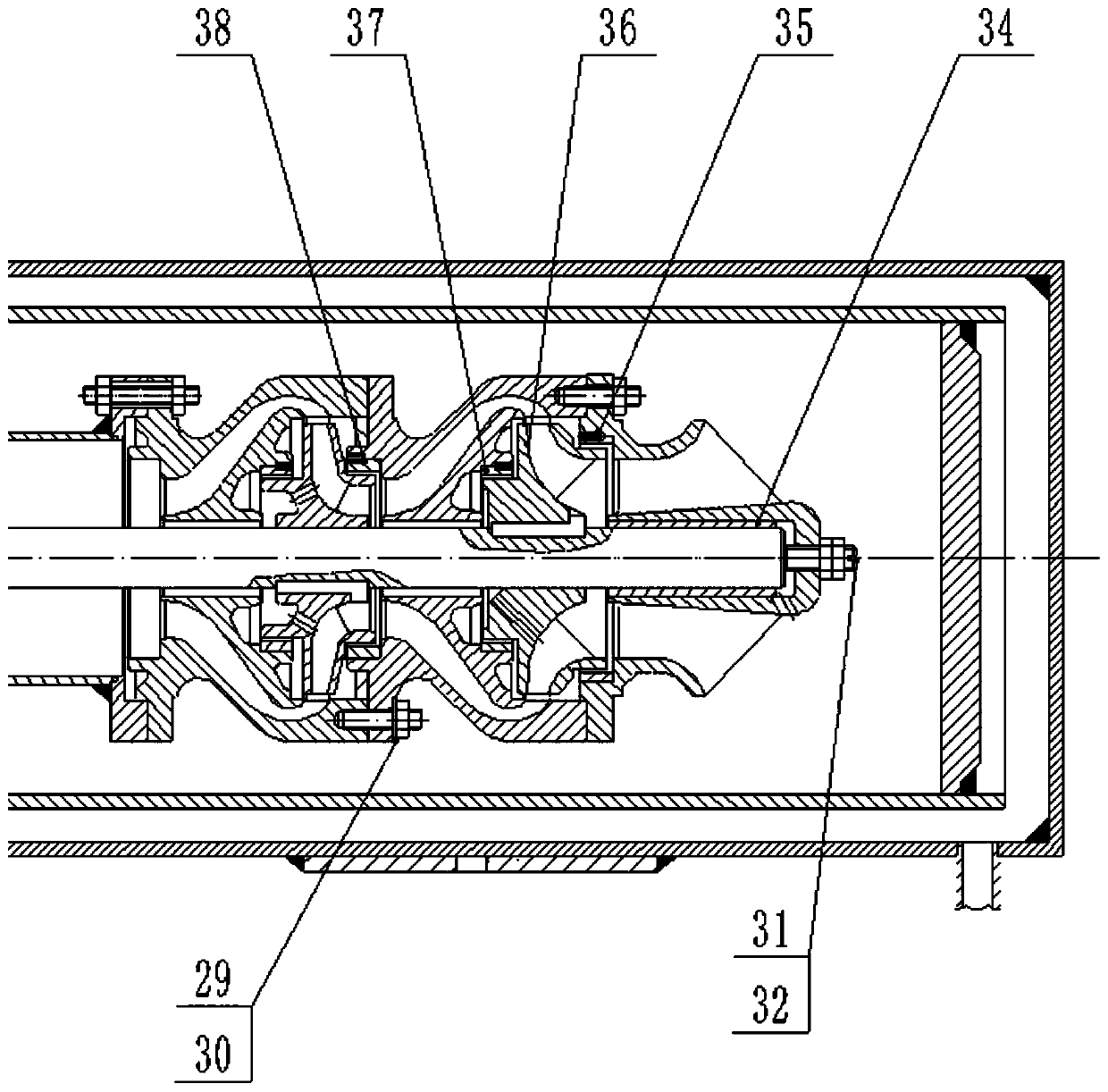
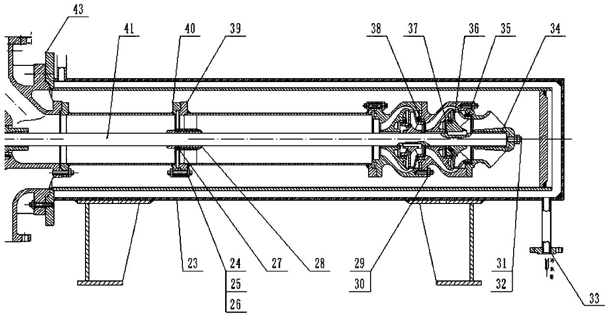
[0026] like Figure 1-Figure 4 As shown, the composite condensate pump of the present invention includes a motor shaft 5, a motor bracket 9, a base 21, a pipe shell 23, a coolant outlet pipe 33, a secondary impeller 36, a bearing joint assembly 39, and a first joint assembly Part 40, pump shaft 41, coolant inlet pipe 42, casing 43, pump outlet cover 44, and second connection assembly 45.

[0027] The motor is fixed to the motor bracket 9 through the outer hexagonal screw 1, the first bolt 8, and the first nut 7; the motor shaft is connected to the pump shaft 41 through the half coupling 3 at the motor end and the coupling key 4 at the driving end; the pump shaft 41 Installed in the pump casing, the connection between the pump casing and the pump shaft 41 is installed with the bearing 20, the sliding bearing sleeve 22...


PUM


Abstract

The invention discloses a combined condensate liquid pump. Connecting pipe combination parts are connected at the discharge end and can play a role in detecting the water flow, the water flow can be controlled more simply, conveniently and intuitively, the influence of a condensation pump device on the intensity of pressure can be reduced, the inner air pressure can be balanced, and the water flowspeed difference is reduced. Secondary condensation is carried out based on the principle of a heat exchanger, the condensation efficiency is improved, meanwhile the condensation process is smootherand steadier by the use of a base, and the device is protected.

Description

technical field [0001] The invention belongs to the field of chemical equipment, in particular to a composite condensate pump. Background technique [0002] Condensation pumps are vacuum pumps that use condensed gas on low-temperature surfaces. Condensation pumps are vacuum pumps with the lowest ultimate pressure and the largest pumping rate for clean vacuum. They are widely used in the research and production of semiconductors and integrated circuits, as well as molecular beam research, vacuum coating equipment, Vacuum surface analysis instruments, ion implanters and space simulation devices. Because of its outstanding advantages such as clean and pollution-free, high efficiency, high pumping speed, and high reliability, it is widely used in many fields such as scientific research laboratories and even industrial production, such as semiconductor material production, flat panel display production / testing equipment, solar energy Manufacturing, vacuum coating, thermal vacuum...

Claims


Application Information

Patent Timeline
Patent Type & Authority Applications(China)
IPC IPC(8): F04D13/06F04D15/00F04D29/22F04D29/24F04D29/58F04D29/66
CPCF04D13/06F04D15/0088F04D29/185F04D29/2222F04D29/242F04D29/5866F04D29/669
Inventor 栾飞荆礼王桯桓源潘博睿刘辰辰于恒哲
Owner SHAANXI UNIV OF SCI & TECH
Why Eureka
Try Eureka