
Solarenergy heat absorber with built-in lens capable of moving in reciprocating mode in axial direction

A solar heat absorber, reciprocating motion technology, applied in solar collectors, solar collectors using working fluid, components of solar collectors, etc., can solve problems such as easy high temperature creep, and achieve extended use life, preventing excessive temperature gradient, preventing high temperature creep and excessive thermal stress

Pending Publication Date: 2019-07-05
HUNAN UNIV OF SCI & TECH
View PDF0 Cites 2 Cited by
  • Summary
  • Abstract
  • Description
  • Claims
  • Application Information

AI Technical Summary

Problems solved by technology

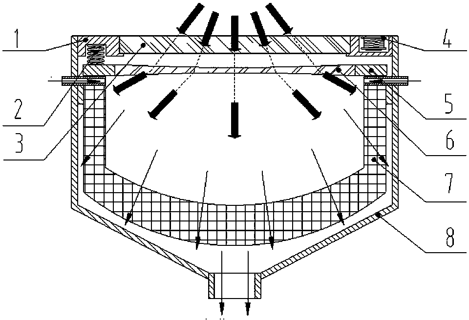
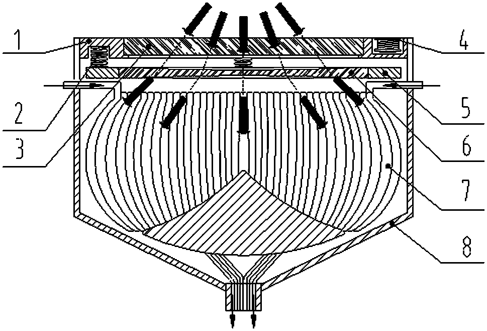
[0003] In order to solve the above technical problems, the present invention provides a simple structure, which can adjust the direction of the solar radiation incident into the heat absorber, so that the solar radiation reaches the surface of the heat exchange medium as uniformly as possible, and improves the transport of solar radiation energy to the heat exchange medium. The efficiency of the medium is a solar heat absorber with a built-in axially reciprocating lens; it can also continuously change the direction of the incident light on the heat exchange medium in real time to avoid excessive concentration of energy flow distribution at a certain point on the heat absorption medium Generate hot spots, which will lead to excessive thermal stress at a certain point and easy high temperature creep, improving service life

Method used


Image

  • Solarenergy heat absorber with built-in lens capable of moving in reciprocating mode in axial direction
  • Solarenergy heat absorber with built-in lens capable of moving in reciprocating mode in axial direction
  • Solarenergy heat absorber with built-in lens capable of moving in reciprocating mode in axial direction

Examples


Embodiment Construction

[0015] The present invention will be further described below in conjunction with the accompanying drawings.

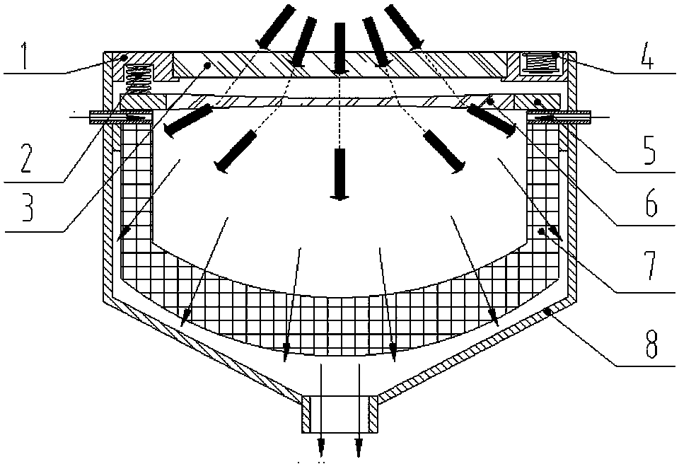
[0016] Such as figure 1 , 2 As shown, the present invention includes an end cover 1 , a quartz glass window 3 , a pulse electromagnet 4 , a lens mounting frame 5 , a non-planar lens 6 , a heat absorbing device 7 and a heat absorber housing 8 . The heat absorbing device 7 is installed in the heat absorber shell 8; the quartz glass window 3 is fixedly installed at the sunlight inlet of the heat absorber shell 8 through the end cover 1. The lens mounting frame 5 is a ring structure, the lens mounting frame 5 is made of magnetic material, and the central hole of the lens mounting frame 5 is provided with a non-planar lens 6; the non-planar lens 6 is a concave lens, a convex lens or a variable parameter non-planar lens.

[0017] The lens mounting frame 5 is made of cast iron and is located in the heat absorber shell 8. It is connected to the end cover 1 through several s...


PUM


Abstract

The invention discloses a solar energy heat absorber with built-in lens capable of moving in a reciprocating mode in the axial direction, which comprises a heat absorber casing, a heat absorbing device, a quartz glass window, a non-planar lens, and a lens mounting rack; the heat absorbing device is mounted in the heat absorber casing; the quartz glass window is fixedly mounted at the sunlight inlet of the heat absorber casing through an end cover; the lens mounting rack is of a ring structure, the lens mounting rack is made of a magnetic material, and the non-planar lens is arranged in the center hole position of the lens mounting rack;the lens mounting rack is located in the heat absorber casing and is connected with the end cover through a plurality of springs; the quartz glass window isparallel to the lens mounting rack; and the end cover is provided with a plurality of pulse electromagnets, the magnetic force between the lens mounting rack and the pulse electromagnets enables thelens mounting rack to be close to the quartz glass window. According to the solar energy heat absorber with built-in lens capable of moving in a reciprocating mode in the axial direction, the direction of solar radiation entering into the heat absorber can be dynamically adjusted, so that the solar radiation can reach the surface of a heat absorbing medium dynamically and uniformly, and the heat conversion efficiency of the heat absorbing device is improved.

Description

technical field [0001] The invention relates to the technical field of solar energy concentrating heat collection and utilization equipment, in particular to a solar heat absorber with a built-in axially reciprocating lens. Background technique [0002] The heat absorber is the carrier that converts the light radiation energy into the heat energy of the working medium in the solar photothermal conversion system, and it often needs to bear the unsteady uneven high-intensity energy flow load when it works. The energy flow distribution and energy-to-heat conversion efficiency of the heat absorber are two important indicators of its design, and its safety and stability will directly affect the normal operation of the system. Traditionally, there are mainly heat absorbers that use coils or porous media for heat exchange. The heat absorbing device is irradiated by high-density and non-uniform energy flux density, which will cause local overheating on the surface of heat exchange m...

Claims


Application Information

Patent Timeline
Patent Type & Authority Applications(China)
IPC IPC(8): F24S23/30F24S60/00F24S10/70F24S80/10F24S80/00
CPCY02E10/44
Inventor 聂笃忠王晓彭佑多颜健米承继曾辉藩刘永祥
Owner HUNAN UNIV OF SCI & TECH
Learn More