Large-scale antenna field directional diagram measuring system and method for multi-rotor unmanned aerial vehicles

A multi-rotor unmanned aerial vehicle, multi-rotor unmanned aerial vehicle technology, applied in antenna radiation pattern, control/adjustment system, non-electric variable control and other directions, can solve the problems of complex large-scale array antenna, inconvenience, etc. Accurate, actionable effects

Inactive Publication Date: 2019-07-05
XIDIAN UNIV
View PDF10 Cites 21 Cited by
  • Summary
  • Abstract
  • Description
  • Claims
  • Application Information

AI Technical Summary

Problems solved by technology

Inconvenience and complexity have always been the difficulties of large array antennas and fixed antennas

Method used


Image

  • Large-scale antenna field directional diagram measuring system and method for multi-rotor unmanned aerial vehicles
  • Large-scale antenna field directional diagram measuring system and method for multi-rotor unmanned aerial vehicles
  • Large-scale antenna field directional diagram measuring system and method for multi-rotor unmanned aerial vehicles

Examples


Embodiment Construction

[0050] The present invention will be described in detail below in conjunction with the accompanying drawings and specific embodiments, where the schematic embodiments and descriptions of the present invention are used to explain the present invention, but not to limit the present invention.

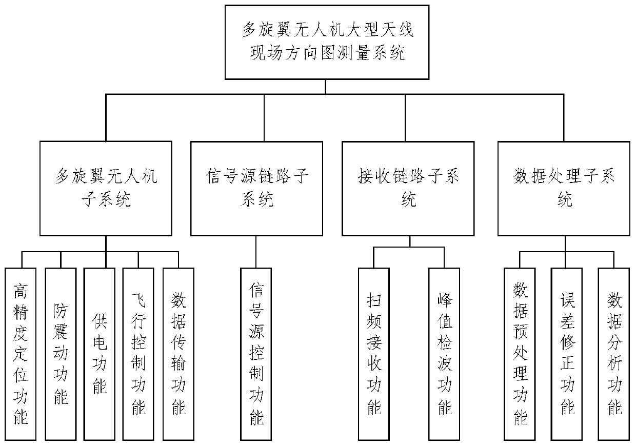
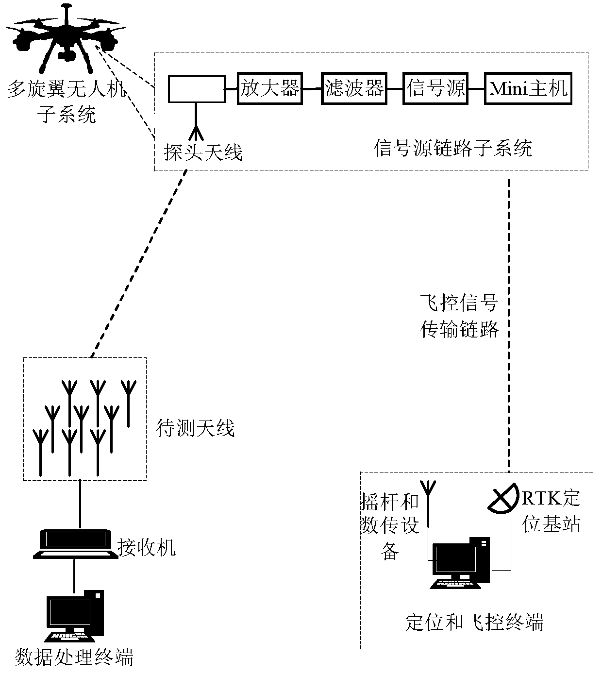
[0051] Such as figure 1 Shown is a functional block diagram of a multi-rotor UAV large-scale antenna field pattern measurement system of the present invention, the system consists of a multi-rotor UAV subsystem, a signal source link subsystem, a receiving link subsystem and a data processing subsystem The system composition is used to obtain the two-dimensional pattern of the large antenna array in the real space, and effectively solve the problem of measuring and evaluating the performance of the large antenna and its array. according to figure 1 Described four subsystems, its corresponding function comprises respectively:

[0052] The multi-rotor drone subsystem is used to stabilize t...


PUM


Abstract

The invention discloses a large-scale antenna field directional diagram measuring system and method for multi-rotor unmanned aerial vehicles. The system includes a multi-rotor unmanned aerial vehiclesubsystem, a signal source link subsystem, a receiving link subsystem and a data processing subsystem. A multi-rotor unmanned aerial vehicle is used to fly at near and far field areas of a to-be-measured antenna according to a set cruise mission; through remote real-time control on a signal source link module, an electromagnetic wave signal in the air can be swept and received in real time; and through the screening, error compensation and data fitting on a received level signal, final directional diagram information can be generated, and the maximum radiation direction, 3dB lobe width, sidelobe level, front-to-back ratios and corresponding position information can be given. On-the-spot directional diagram performance measuring of large-scale antennas under service status can be realized,so that accurate measured data can be provided for fault diagnosis; the system is convenient in operation, high in degree of automation and simple in dismounting; and single sortie flight can accomplish the testing of multifrequency directional diagrams.

Description

technical field [0001] The present invention relates to the technical field of antenna measurement, and more specifically, to a system and method for measuring field patterns of large-scale antennas based on multi-rotor UAVs. Background technique [0002] Accurate knowledge of the radiated performance of large fixed antennas or RF installations throughout the lifetime of the installation is important, for example during system development, system installation and optimization, system handover and acceptance, system modifications and upgrades. The reasons for the degradation of radiation characteristics during use are various, such as aging, wear, pollution, damage from storms or lightning, damage from animals, operating errors, and changes in the surrounding environment. Therefore, periodic quantitative verification and better quality checks of the radiation performance of these systems will become critical. [0003] The traditional large-scale antenna radiation characteris...

Claims


Application Information

Patent Timeline
Patent Type & Authority Applications(China)
IPC IPC(8): G01R29/10G05D1/08G05D1/10
CPCG01R29/10G05D1/0808G05D1/101
Inventor 姜文程通刘鹏席延李昂杰李瑞岚
Owner XIDIAN UNIV
Why Eureka
Try Eureka