Dampproof base of electrical cabinet
A technology for electrical cabinets and protective covers, applied to electrical components, substation/distribution device shells, substation/switch layout details, etc., can solve problems such as inability to clean water droplets in electrical cabinets, damp basements, and high humidity in electrical cabinets. Achieve the effect of preventing moisture from entering the cabinet, ensuring normal operation and accelerating drying
- Summary
- Abstract
- Description
- Claims
- Application Information
AI Technical Summary
Problems solved by technology
Method used
Image

Examples
Embodiment 1
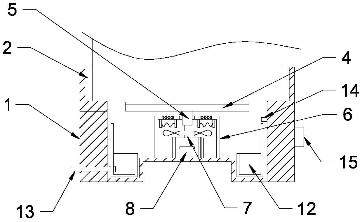
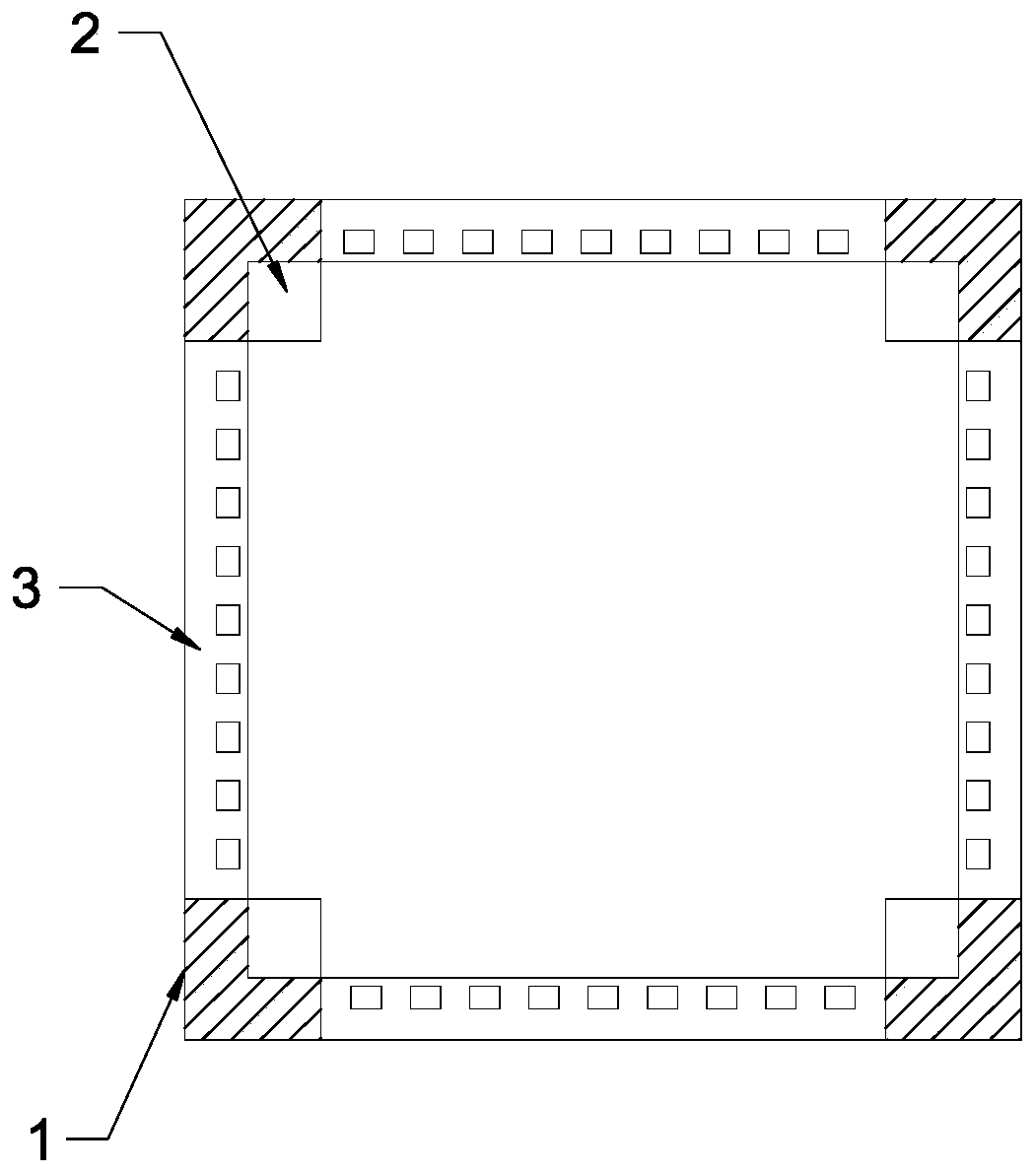
[0021] see figure 1 , in an embodiment of the present invention, a moisture-proof base for an electrical cabinet, including a base body 1; the four corners of the upper end of the base body 1 are provided with snap slots 2 to facilitate the nesting installation of the electrical cabinet on the base body 1; the base body 1 is equipped with a wiper 4, the wiper 4 is fixedly connected with a sleeve 5, the sleeve 5 runs through a protective cover 6, the protective cover 6 is a rectangular box structure, and the sleeve 5 is rotatably connected with the protective cover 6 through a bearing sleeve The sleeve 5 is socketed and fixed with the output shaft 7 of the driving motor 8, and the driving motor 8 is electrically connected to the external power supply. 7 Drive the sleeve 5 and the wiper blade 4 to rotate. The outer side of the wiper blade 4 is provided with an annular water tank 12. The annular water tank 12 is nested in the base body 1 and is connected with a drain pipe 13. Un...
Embodiment 2
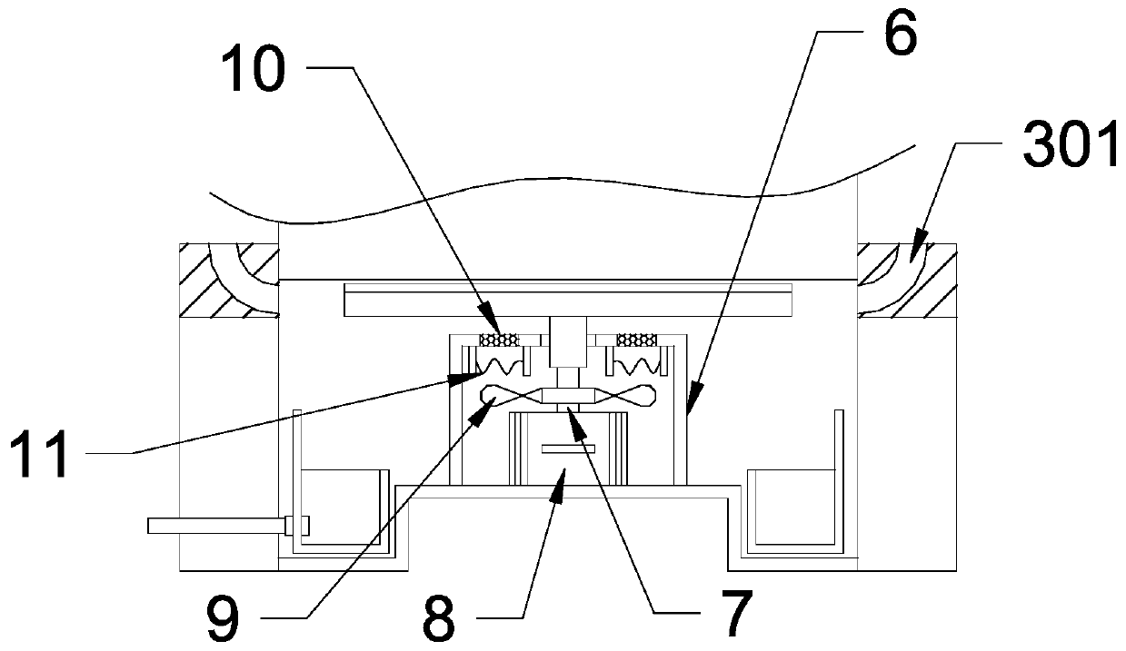
[0023] see Figure 1-4 The difference between this embodiment and Embodiment 1 is: the protective cover 6 is provided with fan blades 9, the fan blades 9 are sleeved on the drive shaft 7, and rotate with the drive shaft 7; the upper end surface of the protective cover 6 is provided with Air outlet holes 10, dust-proof nets are nested in the air outlet holes 10, and the air outlet holes 10 are arranged in a circumferential distribution; a resistance wire 11 is provided under the air outlet holes 10, and the resistance wire 11 is electrically connected to an external power supply, and the power is heated, and the fan blades 9. The resistance wire 11 is blown to generate hot air, and the hot air is discharged from the air outlet 10 and blows to the floor of the cabinet body, and is accelerated to diffuse in the circumferential direction under the action of the wiper blade 4, so as to accelerate the drying of the floor of the cabinet body.
[0024] The upper end surface of the bas...
Embodiment 3
[0026] The difference between this embodiment and embodiment 2 is: please refer to figure 1 , the inner wall of the base body 1 is fixedly connected with a humidity sensor 14, the humidity sensor 14 is electrically connected with a single-chip microcomputer 15, the single-chip microcomputer 15 is fixedly connected with the outer surface of the base body 1, and the single-chip microcomputer 15 is electrically connected with the resistance wire 11 and the drive motor 8 respectively, When the humidity sensor 14 detects that the humidity in the base body 1 is high, the signal is transmitted to the single-chip microcomputer 15, and the single-chip microcomputer 15 starts the drive motor 8 and the resistance wire 11 to dry the cabinet.
PUM
 Abstract
Description
Claims
Application Information
 - Generate Ideas
- Intellectual Property
- Life Sciences
- Materials
- Tech Scout
- Unparalleled Data Quality
- Higher Quality Content
- 60% Fewer Hallucinations
Browse by: Latest US Patents, China's latest patents, Technical Efficacy Thesaurus, Application Domain, Technology Topic, Popular Technical Reports.
© 2025 PatSnap. All rights reserved.Legal|Privacy policy|Modern Slavery Act Transparency Statement|Sitemap|About US| Contact US: help@patsnap.com