
Constant-current constant-voltage wireless charging system based on topology switching

A technology of constant current, constant voltage and wireless charging, which is applied in current collectors, electric vehicles, electrical components, etc., and can solve problems such as large reactive power

Active Publication Date: 2019-07-05
SOUTHWEST JIAOTONG UNIV
View PDF6 Cites 2 Cited by
  • Summary
  • Abstract
  • Description
  • Claims
  • Application Information

AI Technical Summary

Problems solved by technology

[0006] The purpose of the present invention is to provide a constant current and constant voltage wireless charging system based on topology switching, which is suitable for charging batteries and can work stably in two operating modes: constant voltage power supply and constant current power supply, and solves the problem of In the current wireless charging system, two AC switches are used to switch the charging mode. The system has a large reactive power technical problem.

Method used


Image

  • Constant-current constant-voltage wireless charging system based on topology switching
  • Constant-current constant-voltage wireless charging system based on topology switching
  • Constant-current constant-voltage wireless charging system based on topology switching

Examples


Embodiment 1

[0091] Theoretical analysis is carried out aiming at the first scheme adopted in the present invention.

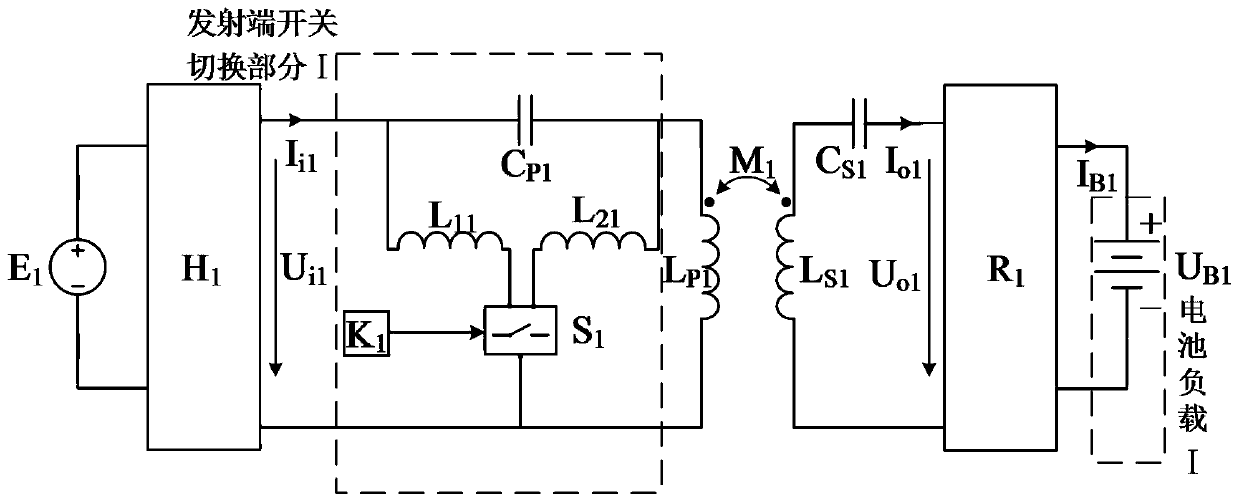
[0092] Such as figure 1 The circuit shown, let C P1 Satisfy C S1 Satisfy which is:

[0093]

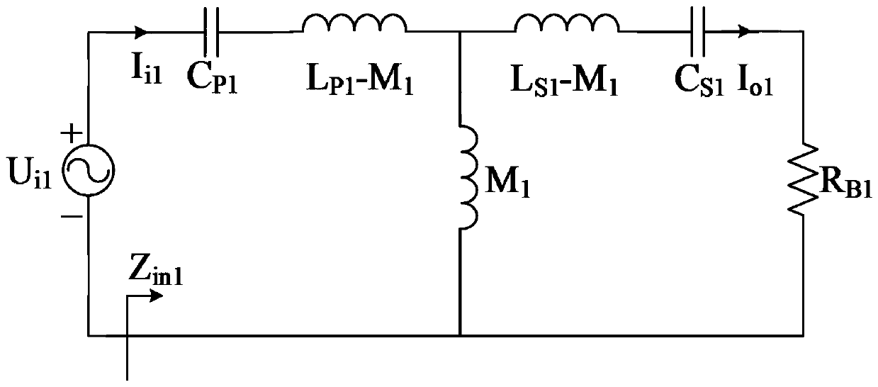
[0094] When switching the switch (S 1 ) is disconnected, the equivalent circuit of the system is as follows image 3 shown. The equivalent impedance of the input end of the system (the output side of the high-frequency inverter) is derived through the principle of series and parallel connection of component impedance, and combined with formula (26) to simplify, the equivalent impedance of the system is obtained as:

[0095]

[0096] Among them, R B1 is the equivalent resistance value of the battery load (I). Equation (26) shows that the high-frequency inverter (H 1 ) The switching element works in a zero-phase switching state, in which there is no reactive power loss.

[0097] According to the principle of impedance shunting in parallel, the AC output current I ...

Embodiment 2

[0113] A theoretical analysis is carried out aiming at the second scheme adopted in the present invention.

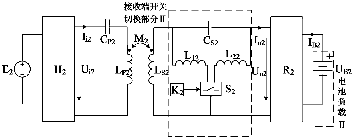
[0114] Such as figure 2 The circuit shown, let C P2 Satisfy C S1 Satisfy which is:

[0115]

[0116] When switching the switch (S 1 ) is disconnected, the equivalent circuit of the system is as follows Figure 4 shown. The equivalent impedance of the input end of the system (the output side of the high-frequency inverter) is derived through the principle of series-parallel connection of element impedance, and combined with formula (33) to simplify, the equivalent impedance of the system is obtained as:

[0117]

[0118] Among them, R B2 is the equivalent resistance value of the battery load (II). Equation (34) shows that the high-frequency inverter (H 2 ) The switching element works in a zero-phase switching state, in which there is no reactive power loss.

[0119] According to the principle of impedance shunting in parallel, the AC output current I ...


PUM


Abstract

The invention discloses a constant-current constant-voltage wireless charging system based on topology switching, and belongs to the field of wireless charging. A switch switching part is disposed ina transmitting part or a receiving part, so that the system can switch between a constant-voltage characteristic and a constant-current characteristic, and is suitable for charging a battery. The switch switching part only has one AC switch and two additional inductors, thereby achieving a small number of components. The equivalent input impedance of the system is pure resistance in both constant-voltage and constant-current modes, namely, the switching device of a high-frequency inverter can work in a zero-phase switching mode in both constant-voltage and constant-current modes, which can effectively reduce the reactive power loss in the system.

Description

technical field [0001] The invention relates to the field of wireless charging, in particular to a constant current and constant voltage wireless charging system based on topology switching. Background technique [0002] Inductive wireless power transmission technology is a technology that uses magnetic field as the medium to realize non-contact power supply. It has the advantages of flexible, safe and reliable power supply, and can avoid potential safety hazards such as sparks and leakage that may exist in traditional contact power supply systems. At present, this technology has been successfully applied to fields such as built-in electronic medical equipment, portable electronic products and contactless power supply of electric vehicles, and has great development potential. [0003] In order to achieve safe charging of the battery, prolong the service life of the battery and the number of charge and discharge times, it usually mainly includes two charging stages of constan...

Claims


Application Information

Patent Timeline
Patent Type & Authority Applications(China)
IPC IPC(8): H02J7/02H02J50/12H02J5/00H02J7/04
CPCH02J5/005H02J7/025H02J7/045H02J50/12
Inventor 麦瑞坤李明轩陈阳杨斌张楠何正友
Owner SOUTHWEST JIAOTONG UNIV
Learn More