
Three-stage treatment equipment for printing and dyeing waste gas

A treatment equipment and three-stage technology, applied in the field of printing and dyeing waste gas three-stage treatment equipment, can solve the problems of reducing waste gas treatment efficiency and single direction of hot air passage, and achieve the effect of improving cooling effect, increasing speed and improving fluidity

Active Publication Date: 2019-07-09
绍兴柯桥佳宇兴腾染整有限公司
View PDF5 Cites 4 Cited by
  • Summary
  • Abstract
  • Description
  • Claims
  • Application Information

AI Technical Summary

Problems solved by technology

With the improvement of the country's exhaust gas emission requirements, environmental protection and waste utilization are advocated, so a three-stage printing and dyeing exhaust gas treatment equipment is proposed to solve the problem of single direction of hot air passage and double sides of zeolite wheel in the process of zeolite concentration. The exhaust gas adsorbed on the surface cannot be quickly detached, which greatly reduces the efficiency of exhaust gas treatment

Method used


Image

  • Three-stage treatment equipment for printing and dyeing waste gas
  • Three-stage treatment equipment for printing and dyeing waste gas
  • Three-stage treatment equipment for printing and dyeing waste gas

Examples


Embodiment

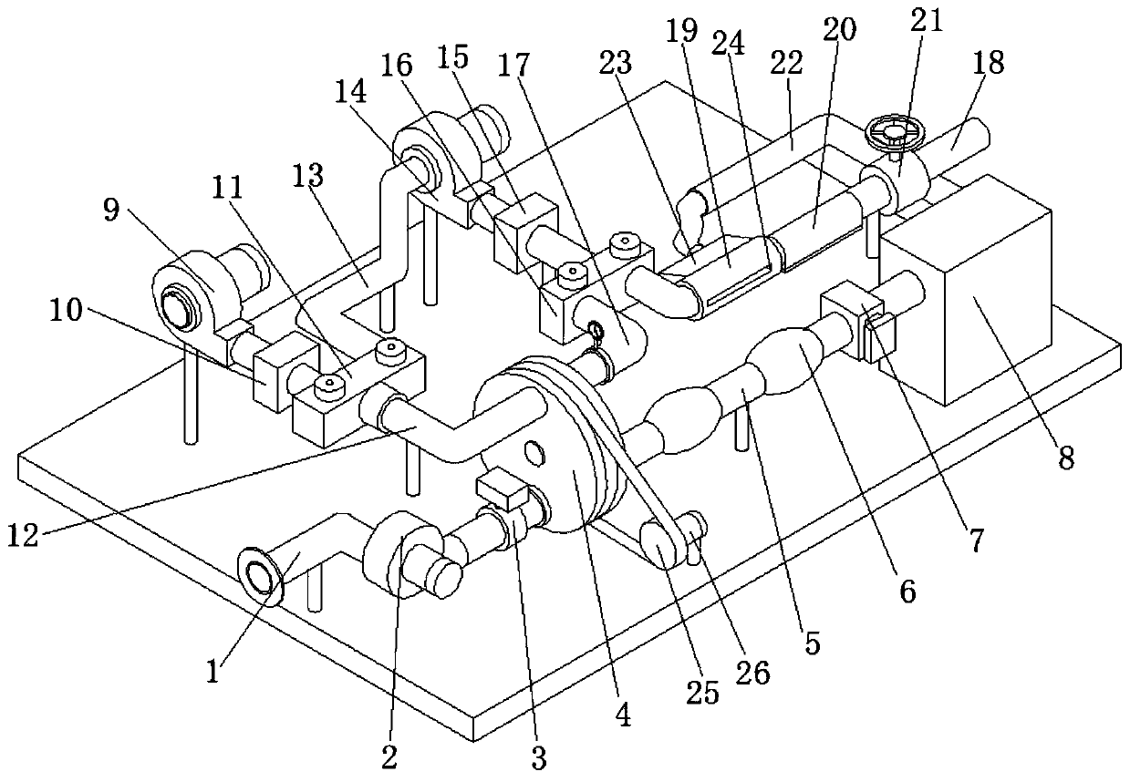
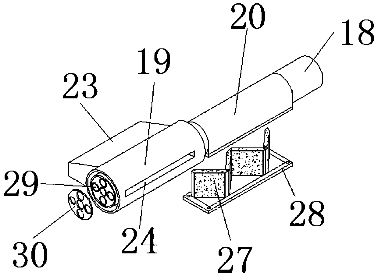
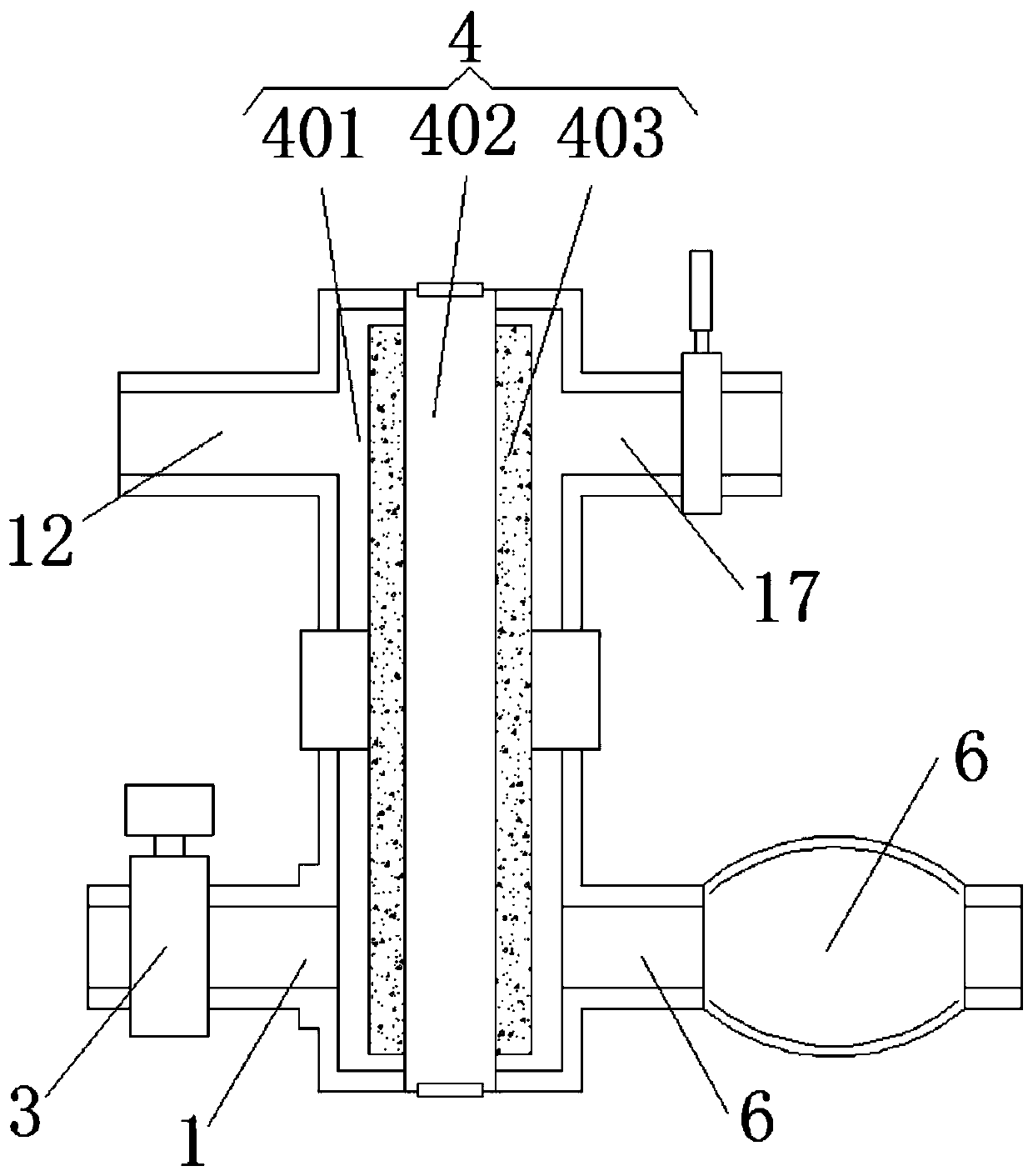
[0025] Embodiment: a kind of printing and dyeing exhaust gas three-stage treatment equipment, such as Figure 1-Figure 4As shown, it includes a support plate, a zeolite concentration device, a waste gas drying device and a photocatalytic degradation device. The zeolite concentration device, the waste gas drying device and the photocatalytic degradation device are all installed on the support plate. , electric butterfly valve 3, zeolite rotating mechanism 4, exhaust pipe 5, booster fan 2 9, electric heating component 10, two-position three-way solenoid valve 11, heat exchange pipe 12, circulation pipe 13, circulation fan 14, Electric heating component 2 15, two-position three-way solenoid valve 2 16 and heat exchange pipe 2 17, the intake pipe 1 is connected to the zeolite rotating mechanism 4, and a booster fan is installed on the outer wall of the intake pipe 1 near the air inlet 12. An electric butterfly valve 3 is installed on the outer wall of the intake pipe 1 close to th...


PUM


Abstract

The invention discloses three-stage treatment equipment for printing and dyeing waste gas. The equipment comprises a supporting plate, a zeolite concentration device, a waste-gas drying device and a photocatalytic degradation device; the zeolite concentration device, the waste-gas drying device and the photocatalytic degradation device are all installed on the supporting plate. When the equipmentprovided by the invention desorb volatile matter adsorbed on zeolite, firstly a booster fan 2 is utilized to drive hot air to pass through the front surface of a zeolite wheel through a heat exchangepipe 1 to take away concentrated waste gas, the waste gas enters a circulation pipe through a heat exchange pipe 2, the circulation pipe communicates with the heat exchange pipe 1 through adjustment of a two-position three-way solenoid valve 1, a circulation fan is started to drive hot air to pass through the back side of the zeolite wheel through the heat exchange pipe 2, then the hot air entersthe circulation pipe through the heat exchange pipe 1, and the air is blown out by the circulation fan from the circulation pipe, so that the equipment realizes circulating flow of an internal airflow, prevents a new air flow from entering the interior, greatly improves the effects of reducing air and increasing the concentration, and makes the waste gas separated thoroughly through blowing of thepositive and negative surfaces of the zeolite wheel.

Description

technical field [0001] The invention relates to the technical field of waste gas treatment, in particular to a three-stage treatment equipment for printing and dyeing waste gas. Background technique [0002] In printing and dyeing production and processing, various dye auxiliaries and coating auxiliaries will be released in the form of organic gases such as formaldehyde, polybenzenes, and aromatic hydrocarbons, which are called VOCs, which are volatile organic compounds. The composition is complex, flammable and explosive, and difficult to decompose. There are many current treatment methods, mainly zeolite concentration + catalytic combustion, photo-oxygen catalytic treatment and dry paint mist filter. With the improvement of the country's exhaust gas emission requirements, environmental protection and waste utilization are advocated, so a three-stage printing and dyeing exhaust gas treatment equipment is proposed to solve the problem of single direction of hot air passage a...

Claims


Application Information

Patent Timeline
IPC IPC(8): B01D53/74B01D53/86B01D53/26B01D53/06
CPCB01D53/06B01D53/26B01D53/74B01D53/86
Inventor 沈兴良高梅林张峰潘李正
Owner 绍兴柯桥佳宇兴腾染整有限公司
Learn More