Steel thin-wall sounding pipe automatic welding device for bored concrete pile

An automatic welding and cast-in-place pile technology, applied in auxiliary devices, welding equipment, auxiliary welding equipment, etc., can solve the problems of high physical fitness requirements of workers, low efficiency of manual welding, and reduced overall construction efficiency, saving resources and reducing energy consumption. Work burden, avoid the effect of manual welding

Inactive Publication Date: 2019-07-09
薛飞
View PDF5 Cites 20 Cited by
  • Summary
  • Abstract
  • Description
  • Claims
  • Application Information

AI Technical Summary

Problems solved by technology

[0003] In the existing building construction, the same batch of short sound measuring tubes will be equipped with the same batch of short sound measuring tubes to complete the welding needs during the work process. The welding of sound measuring tubes generally uses manual welding. The efficiency of manual welding is low and cannot meet the needs of construction. The needs of the operation reduce the efficiency of the overall construction, and in the welding process, it often happens that the straightness of the two steel pipes after welding does not meet the requirements, the scrap rate is high, a lot of resources are wasted, and a large amount of welding is carried out for a long time The job requires a high level of physical fitness for the workers, and its dangers also increase accordingly.

Method used


Image

  • Steel thin-wall sounding pipe automatic welding device for bored concrete pile
  • Steel thin-wall sounding pipe automatic welding device for bored concrete pile
  • Steel thin-wall sounding pipe automatic welding device for bored concrete pile

Examples


Embodiment Construction

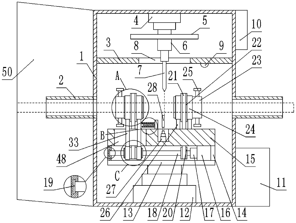
[0022] Below in conjunction with accompanying drawing and specific embodiment the present invention is described in further detail:

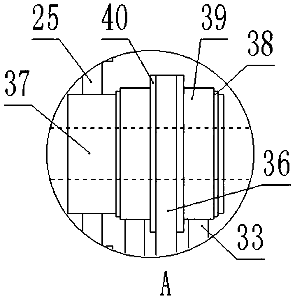
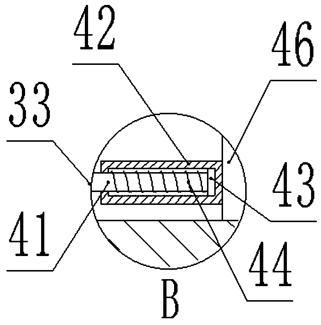
[0023] like figure 1 , figure 2 , image 3 , Figure 4 , Figure 5 , Image 6 , Figure 7 , Figure 8 , Figure 9As shown, a steel thin-walled acoustic tube automatic welding device for concrete pouring piles includes a box body 1, and feeding barrels 2 are symmetrically fixed on both sides of the box body 1, and the axes of the two feeding barrels 2 are arranged opposite to each other. The first hydraulic lifting device 4 is fixedly installed on the inner top surface of the box body 1, and the piston rod at the bottom end of the first hydraulic lifting device 4 is fixedly installed with a baffle plate 5, and the bottom end of the baffle plate 5 is fixedly installed with an automatic A telescopic rod 6, a partition 3 is installed on the top of the box body 1, an opening 8 is fixed at the center of the partition 3, the bottom end of the ...


PUM


Abstract

The invention discloses a steel thin-wall sounding pipe automatic welding device for a bored concrete pile. The welding device comprises a box body, feeding cylinders are symmetrically and fixedly mounted on the two sides of the box body, axes of the two feeding cylinders are oppositely arranged, a first hydraulic lifting device is fixedly mounted on the inner top face of the box body, a baffle isfixedly mounted on a piston rod on the bottom end of the first hydraulic lifting device, the bottom end of the baffle is fixedly provided with an automatic telescopic rod, a partition board is arranged on the top in the box body, and an opening is fixedly formed in the center of the partition board. When the device is used for welding a large batch of steel pipes, traditional manual welding is avoided, work efficiency is increased, time is saved, the whole construction efficiency is improved, the material supply needs are ensured, meanwhile, the problem that the straightness degree after welding of two steel pipes cannot meet the needs is solved, the yield is improved, many resources are saved, through welding in the box body, dangerousness during welding by a worker is reduced, work burdens of workers can be reduced, and the work can be more efficiently finished.

Description

technical field [0001] The invention relates to the field of steel pipe welding devices, in particular to an automatic welding device for steel thin-wall acoustic measuring pipes for concrete pouring piles. Background technique [0002] Steel thin-walled acoustic tubes for concrete pouring piles are needed in building construction. Steel thin-walled acoustic tubes for concrete pouring piles generally refer to pre-embedded steel pipes with a wall thickness of no more than 1.8mm that are used to reserve pipe holes for ultrasonic testing of concrete pouring piles. Referred to as the acoustic tube. The general length of the acoustic tube is 3m, 6m, 9m. The acoustic tube is not allowed to have cracks, scars, folds, delamination, and lap welding defects. The material of the acoustic tube is Q195, Q235, and Q215 in GB / T700. A, B steel. Each batch of acoustic tubes is composed of tubes of the same size, same grade, same material state, and same heat treatment system. When welding...

Claims


Application Information

Patent Timeline
Patent Type & Authority Applications(China)
IPC IPC(8): B23K37/053B23K37/04B23K37/00E02D33/00B23K101/06
CPCB23K37/00B23K37/0435B23K37/0533E02D33/00
Inventor 薛飞李宁
Owner 薛飞
Why Eureka
Try Eureka