
Capillary focusing microbeam X-ray diffractometer

An X-ray and capillary technology, applied in the fields of X-ray diffraction technology and energy dispersive X-ray fluorescence, can solve the problems of complex and expensive equipment, the inability to detect the chemical composition information of samples and the two-dimensional distribution of elements, and reduce power consumption and cost , the effect of increasing the resolution

Inactive Publication Date: 2019-07-09
BEIJING NORMAL UNIVERSITY
View PDF6 Cites 8 Cited by
  • Summary
  • Abstract
  • Description
  • Claims
  • Application Information

AI Technical Summary

Problems solved by technology

[0004] The current conventional X-ray diffraction experimental device has the following defects: (1) cannot realize X-ray diffraction analysis and two-dimensional continuous scanning of the micro-area; (2) cannot detect the chemical composition information of the sample and the two-dimensional distribution of elements; (3) needs High-power X-ray source and circulating water cooling system; (4) complex and expensive equipment

Method used


Image

  • Capillary focusing microbeam X-ray diffractometer
  • Capillary focusing microbeam X-ray diffractometer
  • Capillary focusing microbeam X-ray diffractometer

Examples


Embodiment Construction

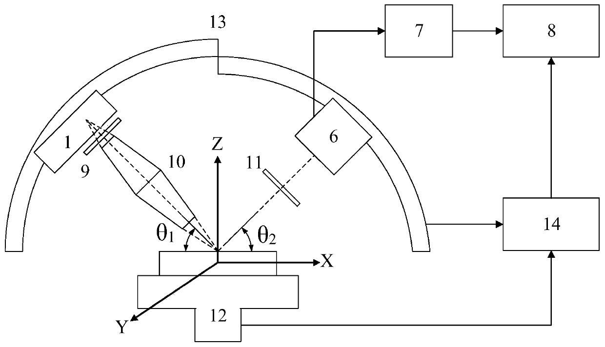
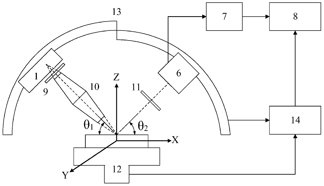
[0023] See attached figure 2 , the present invention provides a micro-beam X-ray diffractometer with capillary focusing, comprising an X-ray source system 1, an X-ray filter 9, a capillary converging X-ray lens 10, a receiving slit 11, a three-dimensional sample stage 12, and a goniometer 13. X-ray detector 6, electronics system 7, control system 14 and computer 8; wherein, X-ray source system 1 consists of Composed of a micro-focus spot X-ray tube of 50 microns and a maximum power of 30 watts, a temperature control device and a cooling fan; the diameter of the X-ray beam spot irradiated on the sample by the capillary converging X-ray lens 10 is 0.1mm, and the spot of the sample to be measured The distance to the capillary converging X-ray lens is 27.6 mm; the length of the receiving slit 11 is 20 mm, and the width is 0.1 mm; the distance from the sample point to be measured to the receiving slit 11 is 62.6 mm, and the receiving slit 11 is to the X-ray detector 6 The distan...


PUM

PropertyMeasurementUnit
Lengthaaaaaaaaaa
Widthaaaaaaaaaa

Abstract

The invention relates to a capillary focusing microbeam X-ray diffractometer, comprising an X-ray source system, an X-ray filter, a capillary convergence X-ray lens, a receiving slit, a three-dimensional sample table, a goniometer, an X-ray detector, an electronics system, a control system and a computer. A sample is placed on the sample table. The X-ray source system, the X-ray filter and the capillary convergence X-ray lens are located on the same straight line and are mounted at one side of the goniometer. The receiving slit and the X-ray detector are located on the same straight line and are mounted at the other side of the goniometer. The X-ray detector is electrically connected with the electronics system and the computer in sequence. The control system is electrically connected withthe three-dimensional sample table, the goniometer and the computer. The diffractometer has two analysis modes of micro-area X-ray diffraction analysis and micro-area energy dispersion X-ray fluorescence analysis. A phase structure of a small sample or a sample micro-area can be measured, and distribution of phases or elements can be detected through two-dimensional continuous scan.

Description

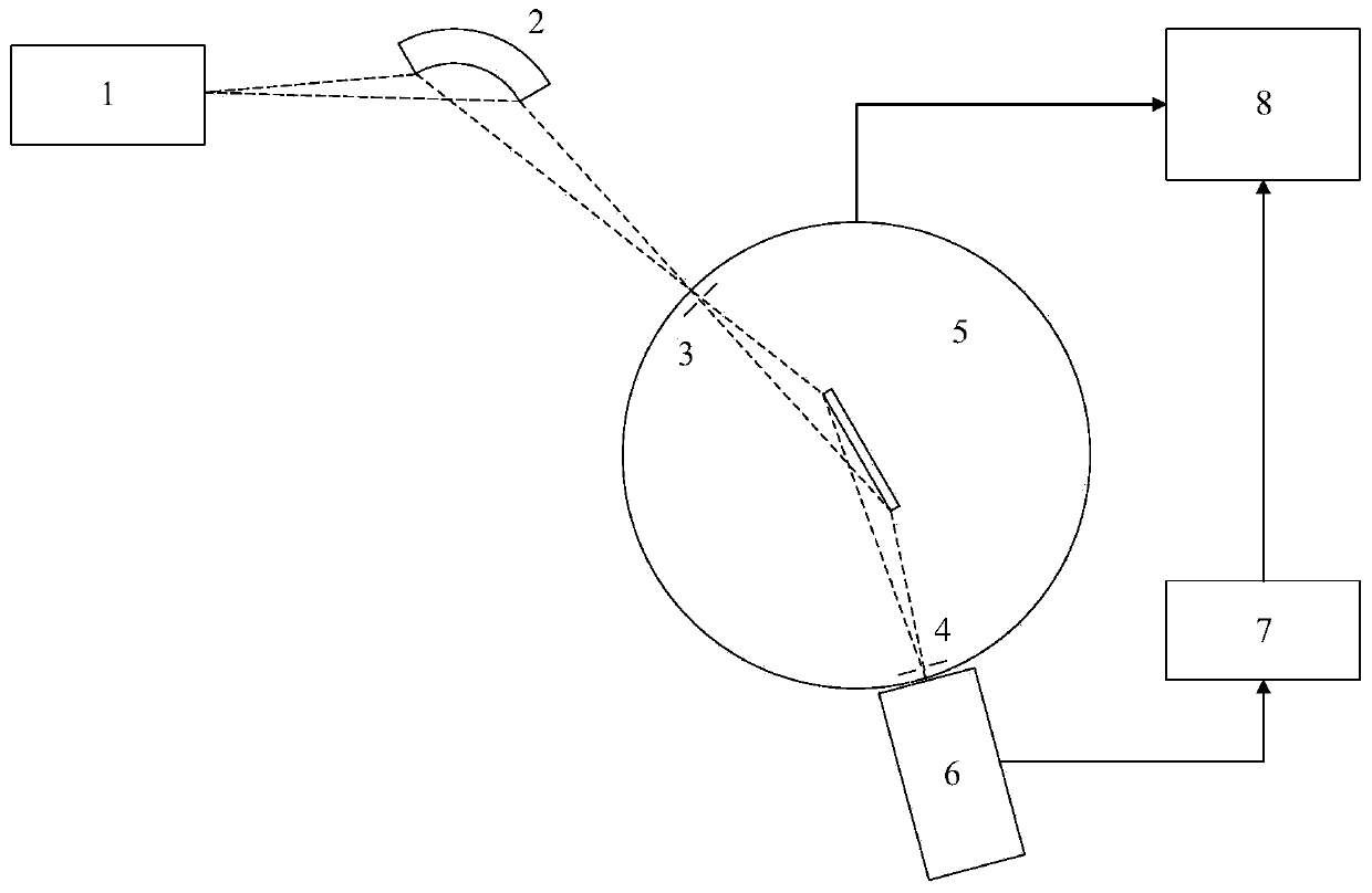
technical field [0001] The invention relates to an X-ray diffraction technique and an energy dispersive X-ray fluorescence technique, in particular to a micro-beam X-ray diffractometer. Background technique [0002] X-ray diffraction analysis is a method of material structure analysis using the diffraction effect of X-rays in crystalline substances. The principle is that when the X-ray emitted from the X-ray source (X-ray tube, etc.) is monochromatized and incident on the surface of a sample with a crystal plane spacing of d, under the condition of Bragg's equation 2dsinθ=nλ, The X-ray detector receives the X-rays diffracted from the sample, and calculates the interplanar spacing d according to the angle θ between the sample plane and the diffracted X-rays, thereby identifying the crystal structure. [0003] Conventional X-ray diffraction experimental equipment such as figure 1 As shown, it consists of X-ray source system 1, monochromator 2, X-ray collimation system 3 and ...

Claims


Application Information

Patent Timeline
IPC IPC(8): G01N23/20008G01N23/223
CPCG01N23/20008G01N23/223
Inventor 程琳姜其立段泽明
Owner BEIJING NORMAL UNIVERSITY
Learn More