Vehicle controller testing method, device and facility
A vehicle controller and test method technology, applied in the direction of program control, general control system, electrical test/monitoring, etc., can solve problems such as high test cost, low efficiency of vehicle R&D, and influence of V process, so as to reduce test cost , shorten the test cycle and improve efficiency
- Summary
- Abstract
- Description
- Claims
- Application Information
AI Technical Summary
Problems solved by technology
Method used
Image
Examples
Embodiment 1
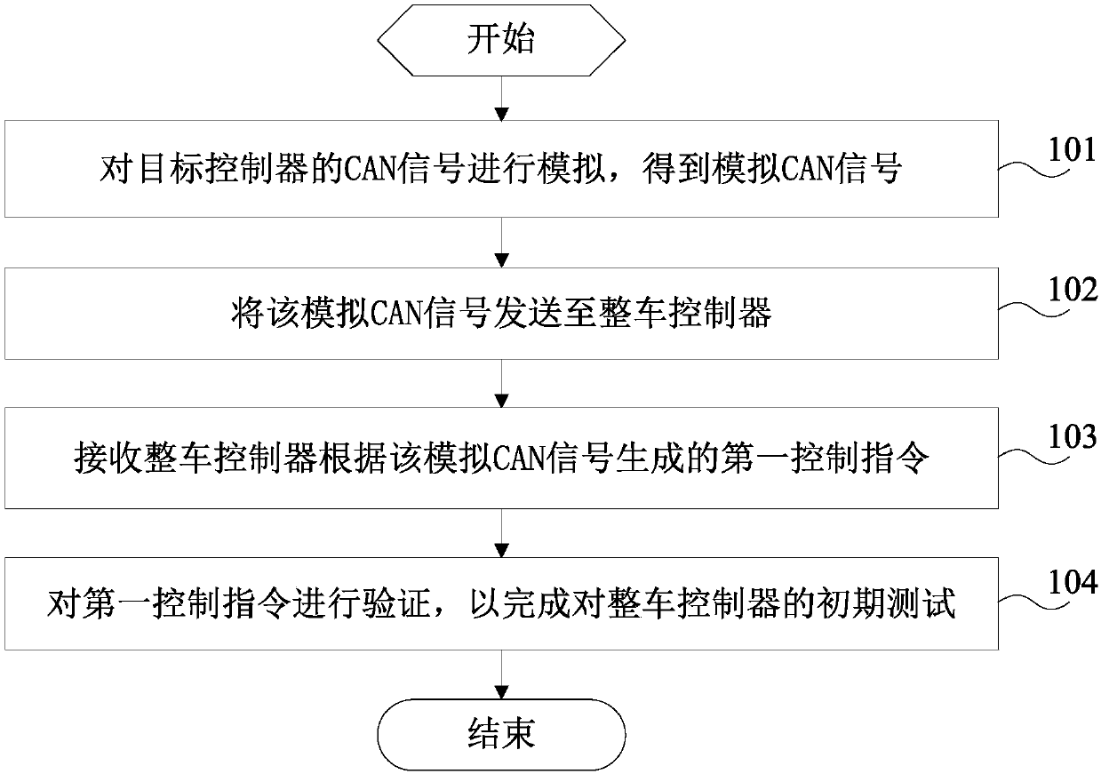
[0061] refer to figure 1 , shows a flow chart of a method for testing a vehicle controller according to an embodiment of the present invention, and the method may specifically include the following steps:
[0062]Step 101, simulating the CAN signal of the target controller to obtain the simulated CAN signal.
[0063] In the early stage of the development of the vehicle controller, the vehicle controller test equipment can perform performance tests on the vehicle controller. First, the vehicle controller test equipment can simulate the CAN signal of the target controller to obtain a simulated CAN signal, so that the CAN signal sending and receiving performance of the vehicle controller can be tested through the simulated CAN signal.
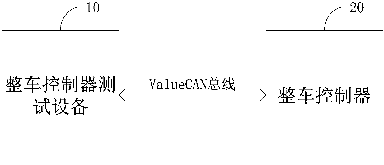
[0064] Among them, the vehicle controller test equipment can use the dbc (Datebase) file to define the CAN matrix, describe the number of nodes on the CAN bus, the address of each node, how each node transmits and receives CAN signals, and the si...
Embodiment 2
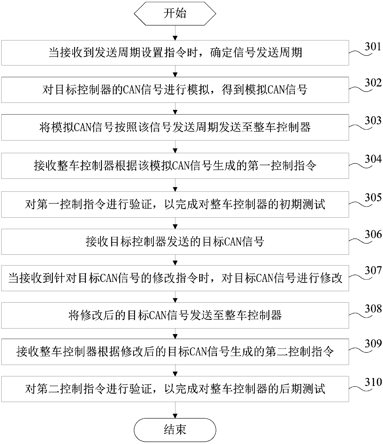
[0077] refer to image 3 , shows a flow chart of another vehicle controller testing method according to an embodiment of the present invention, and the method may specifically include the following steps:
[0078] Step 301, when receiving a sending cycle setting instruction, determine a signal sending cycle.
[0079] During the actual operation of the vehicle, there are usually situations where multiple controllers have CAN signals that need to be sent to the vehicle controller at the same time, and because the vehicle controller will receive CAN signals with higher priority in accordance with the order of priority. Signal, therefore, the controller with low CAN signal priority needs to adjust the signal sending cycle according to its own priority, so as to delay sending the CAN signal. When the priority is different, the signal sending cycle is also different. Therefore, technicians can input the signal transmission cycle in the input box of the test interface, so that when ...
Embodiment 3
[0119] refer to Figure 5 , shows a block diagram of a vehicle controller testing device 500 according to an embodiment of the present invention, and the device 500 may specifically include:
[0120] The simulation module 501 is used to simulate the CAN signal of the target controller to obtain the simulated CAN signal;
[0121] The first sending module 502 is configured to send the analog CAN signal to the vehicle controller;
[0122] The first receiving module 503 is configured to receive the first control instruction generated by the vehicle controller according to the analog CAN signal;
[0123] The first verification module 504 is configured to verify the first control instruction, so as to complete the initial test of the vehicle controller.
[0124] Optionally, the device 500 also includes:
[0125] The second receiving module 505 is configured to receive the target CAN signal sent by the target controller;
[0126] A modification module 506, configured to modify th...
PUM
 Abstract
Description
Claims
Application Information
 - R&D
- Intellectual Property
- Life Sciences
- Materials
- Tech Scout
- Unparalleled Data Quality
- Higher Quality Content
- 60% Fewer Hallucinations
Browse by: Latest US Patents, China's latest patents, Technical Efficacy Thesaurus, Application Domain, Technology Topic, Popular Technical Reports.
© 2025 PatSnap. All rights reserved.Legal|Privacy policy|Modern Slavery Act Transparency Statement|Sitemap|About US| Contact US: help@patsnap.com


