DC charging terminal automatic wire welder

A charging terminal, automatic welding technology, applied in circuits, electrical components, circuit/collector parts, etc., can solve the problems of low degree of automation, high processing efficiency, and long wire transfer time.

Pending Publication Date: 2019-07-09
东莞市科锐思智能设备有限公司
View PDF0 Cites 16 Cited by
  • Summary
  • Abstract
  • Description
  • Claims
  • Application Information

AI Technical Summary

Problems solved by technology

However, there are currently two methods for processing the above-mentioned DC power cables. One is to manually weld the DC terminals, PCB boards, and cut and stripped wires into corresponding DC voltage cable plugs. This method has low processing efficiency. , require large labor force and high production cost; the other is to process through automatic wire welding equipment, and complete processing through automatic equipment, with high processing efficiency and reduced production cost
However, the existing equipment for processing DC power cord plugs still has the following deficiencies: First, the degree of automation is low. The processing of electric wires still uses manual cutting and stripping, which requires manual intervention, and the quality of the processed DC power cord plugs is not good. Second, the processing of the existing DC power cord plugs is completed by multiple devices, and the time for switching between the devices is long, which reduces the processing efficiency and increases the production cost; third, the existing equipment processes out The consistency and quality of the DC power cord plug is not high

Method used


Image

  • DC charging terminal automatic wire welder
  • DC charging terminal automatic wire welder
  • DC charging terminal automatic wire welder

Examples


Embodiment Construction

[0035] The present invention will be described in further detail below in conjunction with the accompanying drawings.

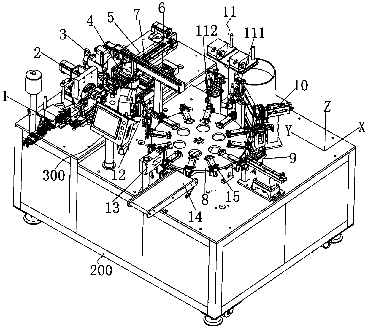
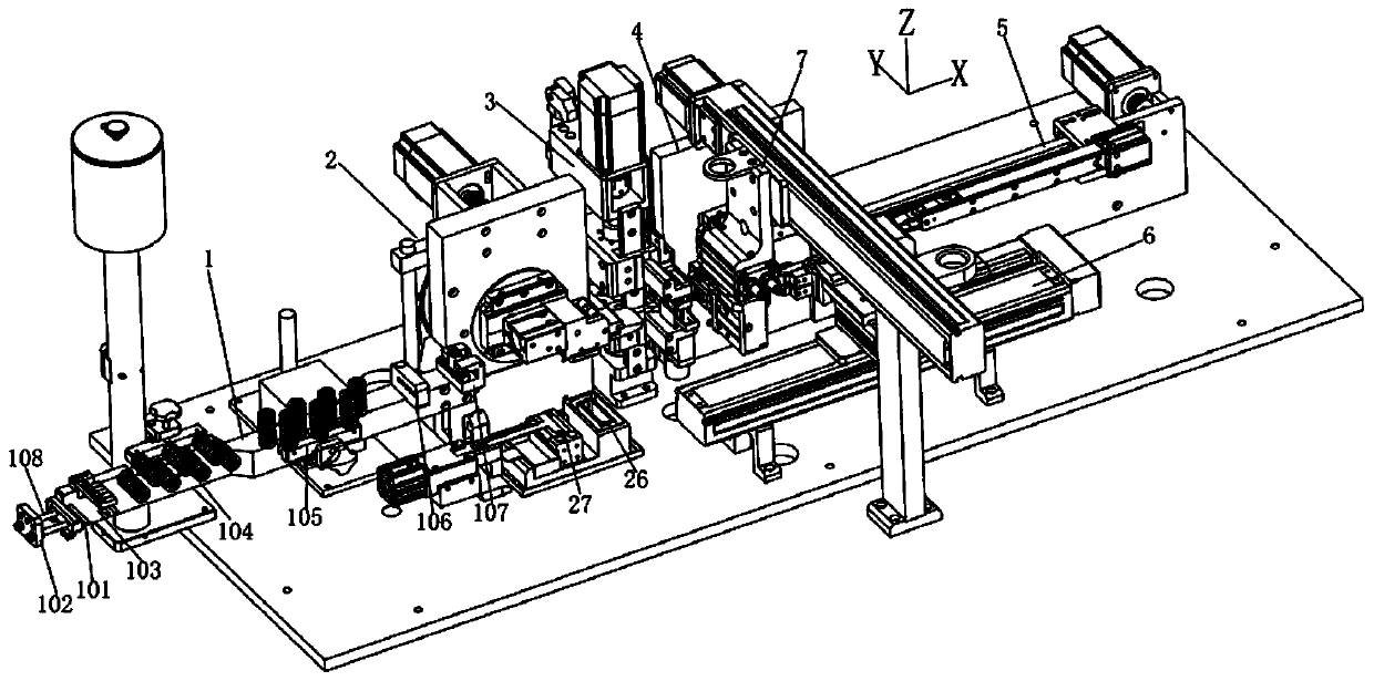
[0036] attached Figure 1-17 Embodiment A kind of embodiment of the present invention, refer to appended Figure 1-17 , an automatic DC charging terminal welding machine, which includes a frame 200 and a control system 300 (PLC controller), and also includes:

[0037] The wire processing mechanism 400 includes a wire passing frame assembly 1, a tinning assembly 2, a wire cutting and stripping assembly 3, a stripping assembly 4, a long pull wire assembly 5, and a pull wire assembly 6 arranged along the X direction of the frame 200 and arranged along the Y direction. The wire feeding assembly 7; the tinning assembly 2, the cutting and stripping assembly 3, the stripping assembly 4, the long pull wire assembly 5, the pull wire assembly 6 and the wire feeding assembly 7 are movable butt joints at the cutting station. Active docking means that the tinning compon...


PUM


Abstract

The invention discloses a DC charging terminal automatic wire welder. The automatic wire welder includes a wire processing mechanism and further includes a wire frame assembly, a tinning assembly, a cutting and stripping assembly, a stripping assembly, a long cable assembly, a cable assembly and a cable feed assembly, wherein the long cable assembly is matched with the cable assembly to pull out two long wires and two short wires with matching length, the cutting and stripping assembly is used for aligning the two long wires and the two short wires with respect to electric wires for cutting and stripping rubber of opposite ends of the electric wires and the long wires/short wires, the stripping assembly is used for stripping the rubber of abutting ends of the long and short wires and the electric wires, the tinning assembly is used for tinning cores of the electric wires and of the abutting ends of the long and short wires, the wire feed assembly is used for transferring the cut two long wires and short wires to the abutting position with of a welding mechanism, and the welding mechanism includes a DC terminal feed assembly, a PCB feed assembly, a spot welding assembly, a multi-point pressure welding assembly, a finished material dispensing assembly and a blanking assembly disposed around the divider.

Description

technical field [0001] The invention relates to the technical field of terminal welding equipment, in particular to an automatic wire welding machine for DC charging terminals. Background technique [0002] Currently, there are many kinds of power cables, such as DC power cables, with figure 1 It is a plug of an existing DC power cord. In the existing technology, it is often necessary to assemble and weld the DC terminal, the PCB board 002 and the wire 003 . However, there are currently two methods for processing the above-mentioned DC power cables. One is to manually weld the DC terminals, PCB boards, and cut and stripped wires into corresponding DC voltage cable plugs. This method has low processing efficiency. 1. The demand for labor is large and the production cost is high; the other is to process through automatic wire welding equipment, and the processing is completed through automatic equipment, which has high processing efficiency and reduced production costs. How...

Claims


Application Information

Patent Timeline
Patent Type & Authority Applications(China)
IPC IPC(8): H01R43/02H01R43/28
CPCH01R43/0256H01R43/28
Inventor 孙树根李良吴广仕肖延枫
Owner 东莞市科锐思智能设备有限公司
Why Eureka
Try Eureka