Driving circuit of laser module of level meter

A laser module and drive circuit technology, applied in circuits, lasers, laser components, etc., can solve the problems of burning laser tubes, large magnification of three-stage tubes, and difficult driving, so as to reduce driving energy, prolong life, increase The effect of drive energy

Pending Publication Date: 2019-07-09
NANJING INST OF RAILWAY TECH
View PDF0 Cites 1 Cited by
  • Summary
  • Abstract
  • Description
  • Claims
  • Application Information

AI Technical Summary

Problems solved by technology

[0004] The problem with the traditional drive circuit is that it adjusts the working state of the laser tube through the amplification performance of the triode, and judges the working state of the laser tube according to the current of the laser tube detected by the photosensitive diode, and the triode adjusts the circuit by itself.
However, (1) due to the large magnification of the triode tube, the circuit consistency is very different, resulting in irregular work of the photosensitive diode, which affects the life of the laser tube; (2) due to the difference between the triode tube and the relationship between the linear region, the laser tube Irregular work; (3) The traditional circuit cannot be adjusted in time according to the external high and low temperature environment, which may easily cause the laser tube to be burned in the high temperature environment, and the laser tube cannot be started in the low temperature environment (based on the characteristics of the laser, at low temperature, the internal molecules of the laser Inactive, difficult to drive, requires a large energy drive to emit light)

Method used


Image

  • Driving circuit of laser module of level meter
  • Driving circuit of laser module of level meter
  • Driving circuit of laser module of level meter

Examples


Embodiment Construction

[0017] The following will clearly and completely describe the technical solutions in the embodiments of the present invention with reference to the accompanying drawings in the embodiments of the present invention. Obviously, the described embodiments are only some, not all, embodiments of the present invention. Based on the embodiments of the present invention, all other embodiments obtained by persons of ordinary skill in the art without creative efforts fall within the protection scope of the present invention.

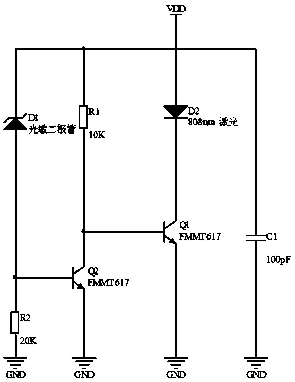
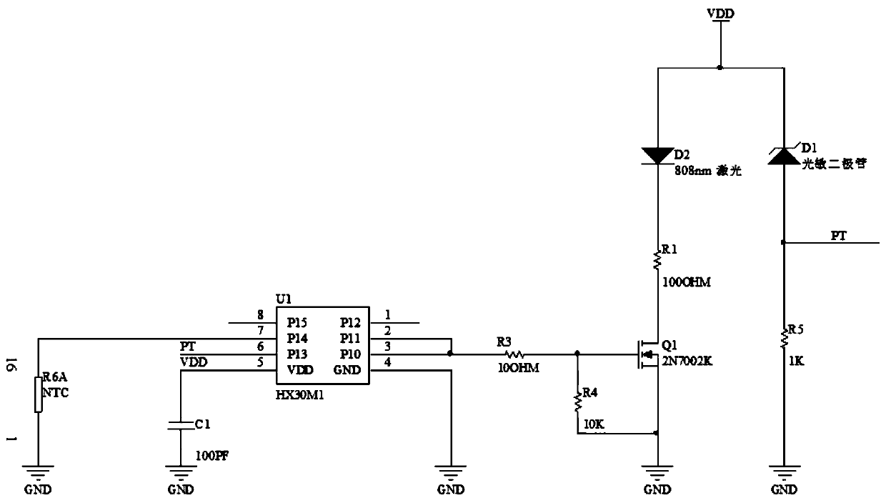
[0018] Such as figure 2 The driving circuit diagram of the laser module of the level meter shown includes the single-chip microcomputer U1, thermistor R6A, power input filter capacitor C1, drive resistor R3, discharge resistor R4, MOS switch Q1, current limiting resistor R1, laser tube D2, photodiode D1 and The feedback resistor R5, wherein, the model of the single chip microcomputer U1 is HX30M1.

[0019] Pin 1 of the thermistor R6A is grounded, and pin 16 of th...


PUM


Abstract

The invention discloses a driving circuit of a laser module of a level meter. In the circuit, a thermistor monitors the ambient temperature. A single chip microcomputer drives an MOS switch to be turned on at a fixed frequency of 100kHZ and a duty cycle of 50%, and thus, a laser tube is turned on. Then, the single chip microcomputer detects the PT signal on a feedback resistor. If the signal is athigh level, it is judged that the light emission is normal. If the laser tube is broken or cannot start due to low temperature, the single chip microcomputer drives the MOS switch to be turned on ata fixed frequency of 100kHZ and a duty cycle of 100% and keeps the MOS switch turned on for 1S to increase the driving energy of the laser tube. At the time, the feedback resistor is switched to highlevel, and driving succeeds. The duty ratio is restored to 50% after 1S. If the feedback resistor is still at low level within 1S, the laser tube is considered to be broken. At high temperature, the frequency is kept at 100kHZ and the duty ratio is kept at 50% to control the energy of the laser tube and solve the problem of damage caused by high temperature. The problem that the photosensitive secondary tube and the laser tube in the traditional circuit work irregularly and the laser tube can easily burn out at high temperature and cannot start at low temperature is solved.

Description

technical field [0001] The invention relates to a laser module drive circuit for a level meter. Background technique [0002] As a measuring instrument, laser level is widely used in construction, home decoration, road and bridge construction and other fields. When in use, the laser tube in the spirit level needs to be driven to emit light through a driving circuit. [0003] The traditional level meter laser module drive circuit such as figure 1 As shown, its working principle is: the external power supply VDD provides 3-3.5V input voltage for the whole circuit, the triode Q1 is driven by the power supply VDD through the resistor R1, the triode Q1 is turned on, and the 808nm laser tube D2 works. The photosensitive diode D1 receives the light from the laser tube D2 and starts to have a reverse photocurrent. When the voltage generated by the current on the resistor R2 is large enough, the transistor Q2 is turned on, the transistor Q1 is cut off, and the laser tube D2 stops w...

Claims


Application Information

Patent Timeline
Patent Type & Authority Applications(China)
IPC IPC(8): H01S5/042G01C9/02
CPCG01C9/02H01S5/042
Inventor 李永芳
Owner NANJING INST OF RAILWAY TECH
Why Eureka
Try Eureka