Lightweight dense insulating bus groove

A busway, light-weight technology, applied in the installation of busbars, cooling busbar devices, fully enclosed busbar devices, etc., can solve the problems of high cost of production equipment, unreached structure, simple process, large workshop area, etc.

Pending Publication Date: 2019-07-09
江苏华鹏电力设备股份有限公司
View PDF5 Cites 0 Cited by
  • Summary
  • Abstract
  • Description
  • Claims
  • Application Information

AI Technical Summary

Problems solved by technology

[0002] The busway products in power transmission and transformation equipment in the power industry have undergone many optimizations, improvements, and updates. From the traditional iron shell busbar to the aluminum alloy shell busbar in the existing technology, the parts material, product structure, and production process have all occurred. After the essential changes, among the busway products of the past dynasties, it has been verified by the market, users and practice that the comprehensive performance is relatively excellent. The CCX-Ⅲ series dense busway is composed of double C-shaped side plates and upper and lower cover plates. The combination of the left and right conjoined side covers with the same or different cross-sections constitutes the SCC series dense busway of the busbar housing. Although the technical structure and production process are simplified to a certain extent, there are still many raw materials consumption and high production equipment costs. The workshop occupies a large area and other problems, and the purpose of simplifying the structure and process has not been achieved

Method used


Image

  • Lightweight dense insulating bus groove
  • Lightweight dense insulating bus groove

Examples


Embodiment Construction

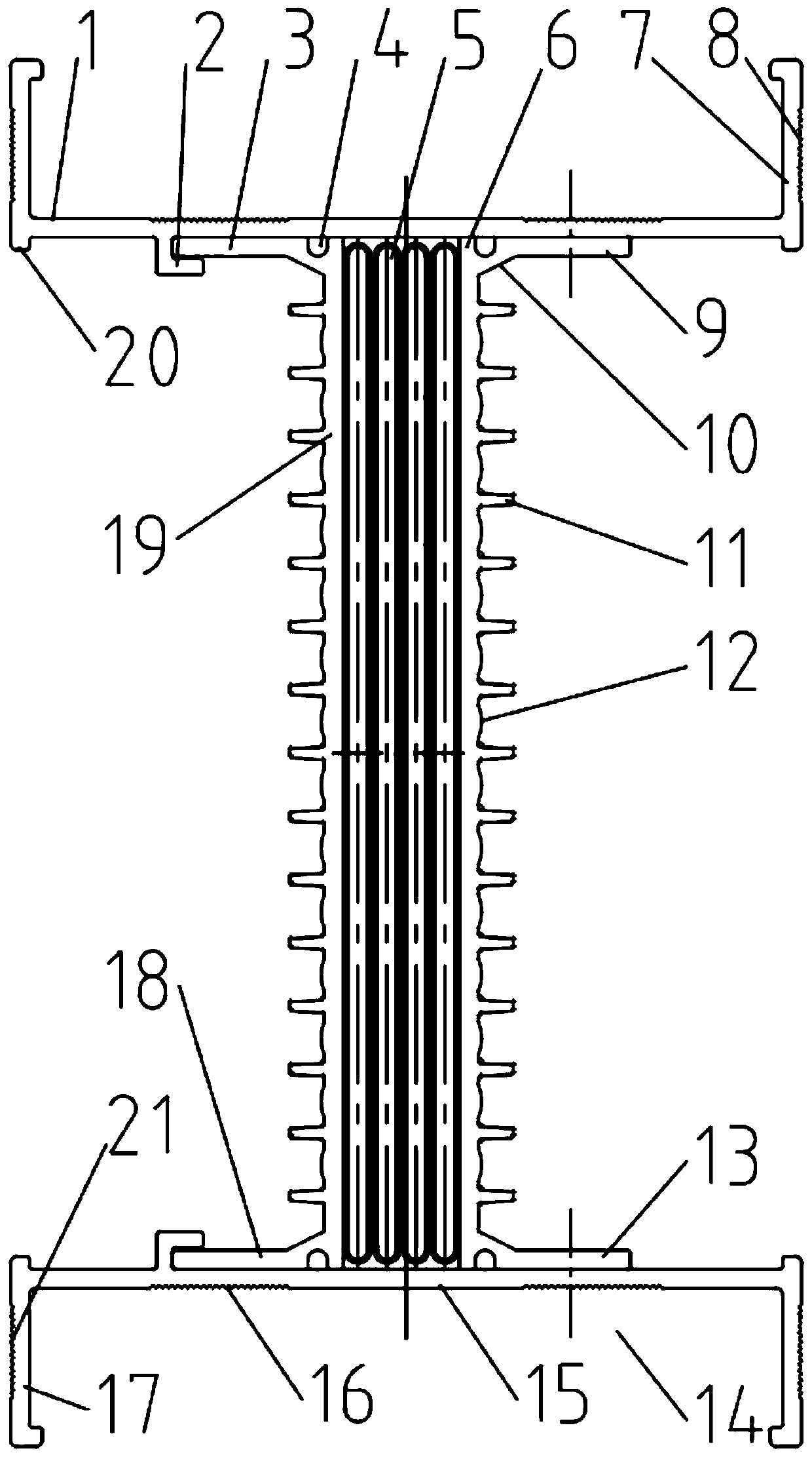
[0018] As shown in the figure, a lightweight dense insulated busway is further improved on the basis of the dense busway in the prior art, including a busbar housing, which includes an upper cover plate 1 and a lower cover plate 15, A left side plate 19 and a right side plate 6 are arranged in the space between the upper cover plate 1 and the lower cover plate 15, and the phase line is surrounded by the upper cover plate 1 and the lower cover plate 15 between the left side plate 19 and the right side plate 6 Conductor placement cavity, the phase line conductor set is tightly clamped in the phase line conductor placement cavity;

[0019] The cross sections of the left side plate 19 and the right side plate 6 are horizontal U-shaped structures facing away from each other. The positions corresponding to the edges are respectively provided with transverse limiting grooves 2, and the upper side 3 and the lower side 17 of the left side plate 19 are respectively limited and clamped o...


PUM


Abstract

The invention relates to a lightweight dense insulating bus groove. A phase line conductor accommodating cavity is formed by the space between a pair of transversely arranged U-shaped left side plateand right side plate which are opposite to each other between an upper cover plate and a lower cover plate. The upper side edge and the lower side edge of the left side plate are respectively limitedand clamped on the upper cover plate and the lower cover plate through limiting grooves. The upper side edge and the lower side edge of the right side plate are respectively riveted and fixedly connected by rivets. The outer side surfaces of the left side plate and the right side plate are provided with multiple reinforcing ribs to increase strength and realize the auxiliary heat radiation function. The heat radiation efficiency is further enhanced by the sawtooth heat radiation grooves. The upper folding edges and the space between the upper folding edges can form a line groove structure fora cable and a signal line, and the space between the lower folding edges can form an auxiliary equipment installation cavity for a lighting lamp, an emergency lamp, a monitoring camera and the like. The outer side surfaces of the upper folding edges and the lower folding edges are provided with anti-slip stripes for convenient handling operation. The structure is simple and compact, the consumption of raw materials is low, the production cost is low, the occupancy area of the workshop is small and the product structure and the production process are all extremely simplified.

Description

technical field [0001] The invention relates to a lightweight dense insulating bus duct. Background technique [0002] The busway products in power transmission and transformation equipment in the power industry have undergone many optimizations, improvements, and updates. From the traditional iron shell busbar to the aluminum alloy shell busbar in the existing technology, the parts material, product structure, and production process have all occurred. After the essential changes, among the busway products of the past dynasties, it has been verified by the market, users and practice that the comprehensive performance is relatively excellent. The CCX-Ⅲ series dense busway is composed of double C-shaped side plates and upper and lower cover plates. The combination of the left and right conjoined side covers with the same or different cross-sections constitutes the SCC series dense busway of the busbar housing. Although the technical structure and production process are simplif...

Claims


Application Information

Patent Timeline
Patent Type & Authority Applications(China)
IPC IPC(8): H02G5/06H02G5/10
CPCH02G5/061H02G5/10
Inventor 殷明郭礼彬匡建华周杰吴雨轩
Owner 江苏华鹏电力设备股份有限公司
Why Eureka
Try Eureka