Eureka AIR delivers breakthrough ideas for toughest innovation challenges, trusted by R&D personnel around the world.

Method and device for feeding rotational flow cushion layer of hydrogenation reactor

A technology for a hydrogenation reactor and a feeding method, which is applied in refining to remove heteroatoms, etc., can solve the problems of difficult adjustment of the flow ratio of the cooling layer and the inner layer, accumulation near the wall of the high temperature vessel, and clogging of pipes, etc. Periodic operation to avoid the effect of condensation reaction coking

Active Publication Date: 2019-07-12
SHANGHAI HUACHANG ENVIRONMENT PROTECTION
View PDF5 Cites 0 Cited by
  • Summary
  • Abstract
  • Description
  • Claims
  • Application Information

AI Technical Summary

Problems solved by technology

[0004] 2. Tar
Because the flow form in the cooling water layer pipe is single, and the flow ratio between the cooling layer and the inner layer is not easy to adjust, and the flow rate of the cooling layer is limited by the interlayer space of the pipeline, the heat exchange effect is not good, and the coking inside the reactor is under high temperature conditions. Raw oil, hydrogen, and catalysts cannot combine and react quickly, and a large amount of coking occurs due to agglomeration. Therefore, only suppressing the rise in temperature cannot effectively suppress the occurrence of coking. To suppress the occurrence of coking in the reactor, the raw oil needs to have good dispersibility after entering the reactor. At the same time, it can quickly combine hydrogen and react with the catalyst
[0009] To sum up, for the hydrogenation reaction process of heavy and low-quality oil, it is very easy to happen: (1) When the feedstock oil enters the pipe, due to the high temperature of the pipe wall, the feedstock oil is polymerized and coked, and the inlet pipe is blocked; (2) For In the case of lateral feedstock oil feeding, inside the hydrogenation reactor, the feedstock oil enters the upper part of the tube and the wall of the hydrogenation reactor to form a negative pressure zone, so that the feedstock oil gathers near the wall of the high temperature device, and coking occurs; (3) After the feedstock oil enters the hydrogenation reactor, if it cannot be dispersed in time, and the combination with hydrogen and catalyst is not timely, polymerization and coking will occur

Method used


Image

  • Method and device for feeding rotational flow cushion layer of hydrogenation reactor
  • Method and device for feeding rotational flow cushion layer of hydrogenation reactor
  • Method and device for feeding rotational flow cushion layer of hydrogenation reactor

Examples


Embodiment 1

[0074] 1. Device name

[0075] 5000L / h ebullating bed hydrogenation reactor cold mold device

[0076] 2. Technological process

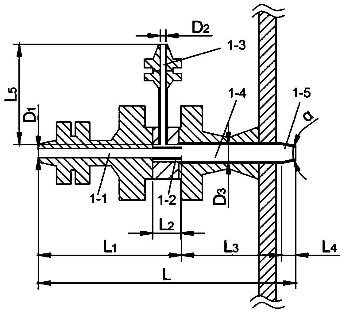
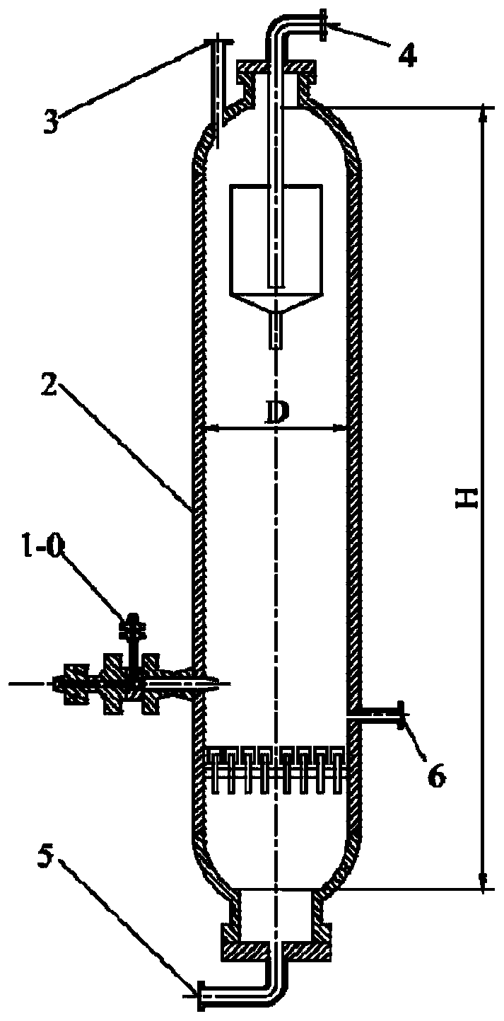
[0077] Such as figure 1 shown. The raw material oil and circulating hydrogen donor enter the reactor from the swirl bed feeder on the side of the hydrogenation reactor. The control range of the feed temperature of the raw material oil and the circulating hydrogen donor is from room temperature to 45° C., and the mass ratio of the circulating hydrogen donor and the raw material oil is controlled to be 0.25-2. The feedstock oil enters the swirl cushion feeder through the feedstock oil axial introduction pipe 1-1, and at the same time, the hydrogen-supply circulating oil enters the ring of the swirl-flow cushion feeder through the swirl introduction pipe 1-3 of the circulating hydrogen supply agent. Gap swirl chamber 1-2, and the swirl flow stream is formed under the diversion action of the swirl blades in the annular gap swirl chamber 1-2. After th...

Embodiment 2

[0085] 1. Device name

[0086] 200 tons / year sludge cracking liquid hydrodeoxygenation unit

[0087] 2. Technological process

[0088] Such as figure 1shown. The raw material oil and circulating hydrogen donor enter the reactor from the swirl bed feeder on the side of the hydrogenation reactor. The control range of the feeding temperature of the raw material oil and the circulating hydrogen donor is from room temperature to 45° C., and the mass ratio of the circulating hydrogen donor and the raw material oil is controlled to be 0.25-5. The feedstock oil enters the swirl cushion feeder through the feedstock oil axial introduction pipe 1-1, and at the same time, the hydrogen-supply circulating oil enters the ring of the swirl-flow cushion feeder through the swirl introduction pipe 1-3 of the circulating hydrogen supply agent. Gap swirl chamber 1-2, and the swirl flow stream is formed under the diversion action of the swirl blades in the annular gap swirl chamber 1-2. After t...

Embodiment 3

[0096] 1. Device name

[0097] 100 tons / year wood chip cracking liquid hydrodeoxygenation device

[0098] 2. Technological process

[0099] Such as figure 1 shown. The raw material oil and circulating hydrogen donor enter the reactor from the swirl bed feeder on the side of the hydrogenation reactor. The control range of the feed temperature of the raw material oil and the circulating hydrogen donor is from room temperature to 45°C, and the mass ratio of the circulating hydrogen donor and the raw material oil is controlled to be 0.25-10. The feedstock oil enters the swirl cushion feeder through the feedstock oil axial introduction pipe 1-1, and at the same time, the hydrogen-supply circulating oil enters the ring of the swirl-flow cushion feeder through the swirl introduction pipe 1-3 of the circulating hydrogen supply agent. Gap swirl chamber 1-2, and the swirl flow stream is formed under the diversion action of the swirl blades in the annular gap swirl chamber 1-2. After...


PUM


Abstract

The invention relates to a method and a device for feeding a rotational flow cushion layer of a hydrogenation reactor, and provides a method for feeding the rotational flow cushion layer of the hydrogenation reactor, which comprises the following steps: (a) enabling raw oil to enter a rotational flow cushion layer feeder to form a raw material oil flow which flows linearly in the axial direction of the rotational flow cushion layer feeder; (b) enabling a circulating hydrogen supply agent to enter the rotational flow cushion layer feeder to form a circulating hydrogen supply agent flow which istightly attached to the inner wall surface of the rotational flow cushion layer feeder to perform rotational flow movement; (c) enabling the circulating hydrogen supply agent to be in close contact with the inner wall of the rotational flow cushion layer feeder and in swirling motion; enabling the raw oil to flow linearly along the axial direction of the rotational flow cushion layer feeder so that the circulating hydrogen supply agent can wrap the raw oil; (d) shear-mixing the circulating hydrogen supply agent obtained in the step (c) with the raw oil; (e) spraying the mixed stream of the raw oil obtained in the step (d) and the circulating hydrogen supply agent into the hydrogenation reactor in an umbrella form. The invention further provides the device for feeding the rotational flow cushion layer of the hydrogenation reactor.

Description

technical field [0001] The disclosure belongs to the field of chemical industry, and relates to a feeding method and device for preventing coking when heavy and low-quality oil participates in hydrogenation. Specifically, it relates to a method and a device for feeding a hydrogenation reactor swirling cushion layer. Background technique [0002] The current hydrogenation route and decarbonization route are two major types of heavy oil processing processes adopted by my country's oil refining industry. The hydrogenation process mainly includes ebullating bed hydrogenation, fixed bed hydrogenation, suspension bed hydrogenation, moving bed hydrogenation, etc.; decarbonization The process mainly includes visbreaking, delayed coking, heavy oil catalytic cracking, etc. Regardless of the hydrogenation process or the decarburization process, they all face the problem of coking and coking, which has major hidden dangers to the process continuity, safety and operation stability of ind...

Claims


Application Information

Patent Timeline
Patent Type & Authority Applications(China)
IPC IPC(8): C10G45/02
CPCC10G45/02
Inventor 遆王强汪华林李剑平黄渊常玉龙付鹏波崔馨许德建
Owner SHANGHAI HUACHANG ENVIRONMENT PROTECTION
Why Eureka
Eureka Blog
Learn More