Device and method for distinguishing ureters and blood vessels

A technology for ureters and blood vessels, applied in the field of optical recognition, can solve problems such as inability to judge ureters and blood vessels

Active Publication Date: 2019-07-16
HENAN UNIVERSITY
View PDF8 Cites 5 Cited by
  • Summary
  • Abstract
  • Description
  • Claims
  • Application Information

AI Technical Summary

Problems solved by technology

[0004] In order to solve the problem that the ureter and blood vessel in the human body cannot be quickly and accurately judged in the prior art, the present inventio...

Method used


Image

  • Device and method for distinguishing ureters and blood vessels
  • Device and method for distinguishing ureters and blood vessels
  • Device and method for distinguishing ureters and blood vessels

Examples


Embodiment 1

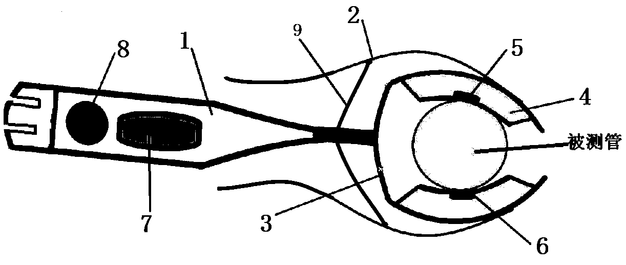
[0061] Embodiment 1: as Figure 1 to Figure 7 As shown, a device for distinguishing ureters from blood vessels includes a handle 1 and a clip body arranged at the front end of the handle 1. The clip body includes a clip handle 2 and a clip head 3. The clip head 3 is arc-shaped, and the clip body The top and bottom of the outside of the head 3 are respectively provided with clamping handles 2, and each of the clamping handles 2 is in the shape of a transitional arc; a connecting rod 9 is arranged obliquely between the clamping handle 2 and the handle 1, and one end of the connecting rod 9 is connected to the handle 1. Fixedly connected, the other end is hinged with the clamp handle 2;

[0062] The upper and lower sides of the chuck 3 are provided with arc-shaped rubber pads 4 that fit the chuck 3. The rubber pads 4 are respectively equipped with detection units, and the two rubber pads 4 are used to clamp the tube under test. ;

[0063] The handle 1 is provided with a display...

Embodiment 2

[0073] Embodiment 2: as Figure 8 As shown, a method for discriminating ureters and blood vessels based on a device for discriminating ureters and blood vessels comprises the following steps:

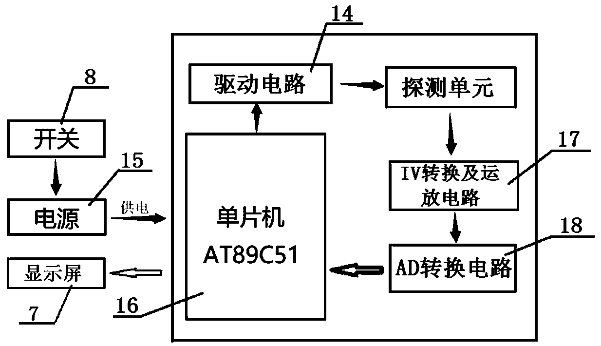
[0074] Step 1: Clamp the tube under test with the clamp 3; specifically, hold the clamp handle 2 and press it to make the clamp 3 open, then clamp the tube under test, and then let go, so that the side wall of the tube under test is in contact with the The rubber pad 4 inside the chuck 3 fits together so that the detection unit can accurately detect the tube under test, and then turn on the switch 8 for detection.

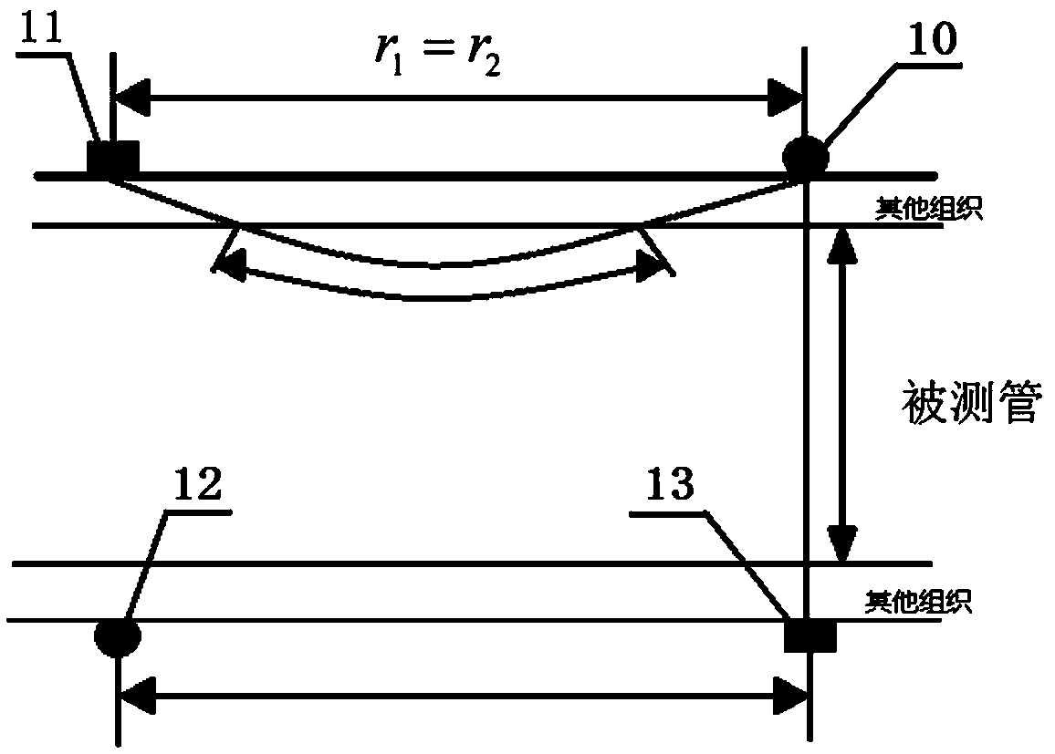
[0075] Step 2: The single-chip microcomputer controls the first light source 10 through the drive circuit 14 to sequentially emit a wavelength of λ 1 and lambda 2 The incident light, the light intensity of the incident light is I 01 and I 02 , and have:

[0076]

[0077] Among them, a is a constant.

[0078] Step 3: The first photodetector 11 detects that the wavele...


PUM


Abstract

The invention relates to a device for distinguishing ureters and blood vessels. The device comprises a handle and a clamping body arranged at the front end of the handle, the clamping body comprises clamping handles and a clamping head, the upper part and the lower part of the outer side of the clamping head are respectively provided with the clamping handles, the inner side of the clamping head is provided with arc-shaped rubber pads which fit the clamping head in a up-down corresponding manner, and detection units are correspondingly arranged in the rubber pads respectively; a display screenand a switch are arranged on the handle, and a power supply and a processing unit are arranged in the handle. The invention also relates to a method for distinguishing ureters and blood vessels. Themethod comprises the following steps: a tube to be tested is clamped; a single-chip microcomputer controls a first light source to sequentially emit incident light, a first photoelectric detector detects the light intensity of reflected light, and a second photoelectric detector detects the light intensity of transmitted light; the obtained light intensity is converted into a digital signal and sent to the single-chip microcomputer; and the single-chip microcomputer analyzes and processes the light intensity, judges that the tube to be tested is a blood vessel or a ureter, and performs calibration. The invention realizes accurate discrimination of blood vessels and ureters in a human body.

Description

technical field [0001] The invention relates to the technical field of optical recognition, in particular to a device and method for distinguishing ureters and blood vessels. Background technique [0002] In clinical surgery, especially in abdominal or pelvic surgery, it is usually necessary to operate on the blood vessels in the operation, but because the surface of the ureter and blood vessels are covered with tissue components such as fat, the tissue adhesion is relatively heavy, so the surgeon cannot dissect the ureter normally , the relationship between blood vessels and surrounding tissues, it may also be due to various reasons such as insufficient experience of the surgeon, lack of familiarity with the direction of normal ureters and blood vessels, etc., which may cause accidental injury or even necrosis of the ureter. Once the ureter is damaged, it will cause various complications. , such as urogenital fistula, hydronephrosis, renal function damage, and even acute re...

Claims


Application Information

Patent Timeline
IPC IPC(8): A61B5/00
CPCA61B5/0059
Inventor 张锦龙杨宇荆雅洁樊琳琳张峰
Owner HENAN UNIVERSITY
Why Eureka
Try Eureka