
Rotatable chisel plugging and unplugging device for wall body material production

A wall material, rotary drive technology, applied in auxiliary molding equipment, ceramic molding machines, manufacturing tools, etc., can solve the problems of high cost of positioning mechanism, difficult maintenance, low production efficiency, etc. Space, the effect of improving production efficiency

Pending Publication Date: 2019-07-16
深圳市宏开轻质墙体材料有限公司
View PDF0 Cites 1 Cited by
  • Summary
  • Abstract
  • Description
  • Claims
  • Application Information

AI Technical Summary

Problems solved by technology

[0003] In order to ensure the strength of the aerated concrete slab and the convenience of transportation, during the production process of the aerated concrete slab, it is necessary to bury the steel mesh cage, and the steel rod of the steel mesh cage hanger carries the steel mesh cage into the mold for fermentation. In liquid concrete, after the fermentation time is sufficient, the steel drill and the steel mesh cage are separated to separate the two. At present, the separation of the steel drill and the mesh cage is usually performed by a plug-in drill machine. The existing plug-in drill machine has a single function. It can only realize the functions of lifting, lowering and walking, and cannot be rotated. When it is necessary to replace the position of the plug-in and pull-out, the plug-in and pull-out device needs to be reassembled. The operation is complicated, the production efficiency is low, and the space of the processing site cannot be used effectively. During the walking process of the brazing device, there are technical problems such as low positioning accuracy, high cost of positioning mechanism, and difficult maintenance

Method used


Image

  • Rotatable chisel plugging and unplugging device for wall body material production
  • Rotatable chisel plugging and unplugging device for wall body material production
  • Rotatable chisel plugging and unplugging device for wall body material production

Examples


Embodiment 1

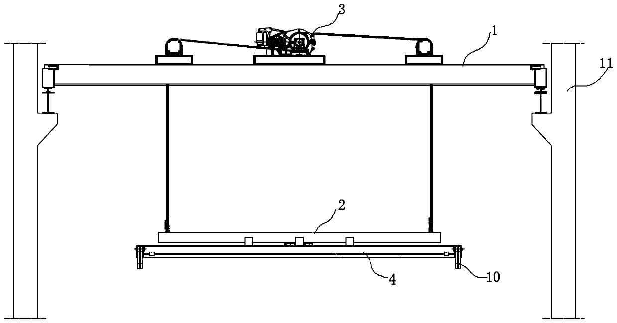
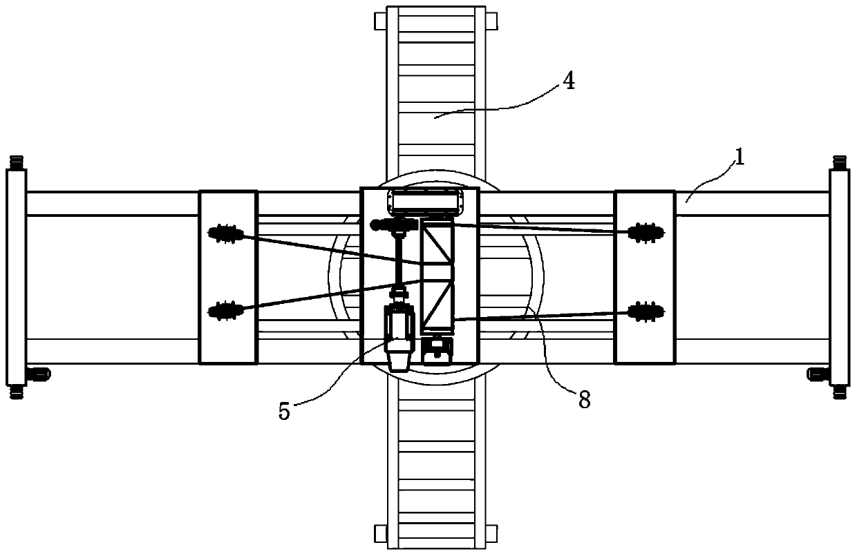
[0035] This embodiment provides a rotatable plug-in device for the production of wall materials, please refer to Figure 1-4 , the rotatable plug-in brazing device includes:

[0036] The horizontal walking vehicle frame 1 is used for reciprocating walking in the horizontal direction.

[0037] The vertical traveling frame 2 is arranged at the bottom of the horizontal traveling frame 1, and the vertical traveling frame 2 is connected with the horizontal traveling frame 1 through a lifting mechanism 3. In this embodiment, the lifting mechanism 3 It is a winch, which is used for vertically lifting the vertical traveling vehicle frame 2 to make the vertical traveling vehicle frame 2 reciprocate in the vertical direction.

[0038] The rotating saddle frame 4 is arranged at the bottom of the vertical walking support 2 and can rotate relative to the vertical walking support 2 . The two ends of the rotating saddle frame 4 are connected with clamps 10 for clamping materials.

[0039] ...


PUM


Abstract

The invention discloses a rotatable chisel plugging and unplugging device for wall body material production. The rotatable chisel plugging and unplugging device comprises a horizontal walking frame, avertical walking frame, a rotary saddle tree and a rotary drive assembly. The vertical walking frame is arranged at the bottom of the horizontal walking frame and connected with the horizontal walking frame through a lifting mechanism. The rotary saddle tree is arranged at the bottom of the vertical walking frame, and can rotate relative to the vertical walking frame. The rotary drive assembly isconnected with the rotary saddle tree and used for driving the rotary saddle tree to rotate in the horizontal direction. The saddle tree is driven by rotate by driving the rotary drive assembly, therotating function of the saddle tree is achieved, compared with an existing chisel plugging and unplugging machine, the rotatable chisel plugging and unplugging device has the functions of horizontalwalking, vertical lifting and rotating, the working range is widened, the site space is effectively utilized, the time for assembling the chisel plugging and unplugging device again is saved, and theproduction efficiency is improved.

Description

technical field [0001] The invention belongs to the technical field of aerated concrete production, and relates to a plug-in and pull-out device, in particular to a rotatable plug-in and pull-out device for wall material production. Background technique [0002] Autoclaved aerated concrete slab is a new type of wall material with light weight, heat preservation, heat insulation, fire prevention and other properties. It is made of fly ash (or silica sand), cement, lime, etc. Air-entrained concrete panels generally contain treated steel bars to improve their strength. As a wall maintenance material, autoclaved aerated concrete slabs have superior performance and are widely used. [0003] In order to ensure the strength of the aerated concrete slab and the convenience of transportation, during the production process of the aerated concrete slab, it is necessary to bury the steel mesh cage, and the steel braze of the steel mesh cage hanger carries the steel mesh cage into the m...

Claims


Application Information

Patent Timeline
Patent Type & Authority Applications(China)
IPC IPC(8): B28B17/00B28B23/02
CPCB28B17/00B28B23/02
Inventor 蔡茂华
Owner 深圳市宏开轻质墙体材料有限公司
Learn More