High-efficiency super-surface device for realizing large field of view imaging based on dielectric continuous structure

A large field of view, high-efficiency technology, used in instruments, optical components, polarizing components, etc., can solve the problems of large number of lenses, high cost, limited application scope, etc., achieve high diffraction, realize polarization detection, and solve the number of lenses. many effects

Active Publication Date: 2019-07-16
INST OF OPTICS & ELECTRONICS - CHINESE ACAD OF SCI
View PDF2 Cites 2 Cited by
  • Summary
  • Abstract
  • Description
  • Claims
  • Application Information

AI Technical Summary

Problems solved by technology

At present, there are mainly four methods: the first is to obtain a focal plane array of large-scale pixels through mechanical splicing of multiple small-scale detectors. This method is difficult to achieve seamless splicing, and faces the problem of focal plane array The problem of peripheral circuit design, and requires expensive and huge optical system. This technology is mainly used in large-scale astronomical telescopes; the second is to scan and stitch images through a single high-resolution lens. This method is relatively mature and can be realized in engineering. It is relatively easy, but the time delay between the stitched fields of view caused by field of view scanning determines that this imaging technology is only suitable for observing static or quasi-static scenes, and the application range of this technology is limited; Two high-resolution lenses shoot images at the same time, and obtain full-field high-pixel images through post-stage image stitching. This method solves the time delay problem of single-lens scanning imaging and does not require a rotating mechanism, but the entire system is composed of multiple lenses. Huge size and high cost; the fourth is a multi-scale optical system, which consists of a front-end objective lens and a rear-end micro-camera array, integrating the large field of view collection capability of the objective lens and the local field of view correction capability of the micro-camera, the system structure Compact, it is an effective means to realize large field of view and high resolution imaging
Based on the above demand background and technical status, it can be seen that the current large field of view imaging still stays under the design paradigm dominated by the traditional geometric optical system, and there are many limitations such as a large number of lenses, complex lenses, and limited real-time performance.

Method used


Image

  • High-efficiency super-surface device for realizing large field of view imaging based on dielectric continuous structure
  • High-efficiency super-surface device for realizing large field of view imaging based on dielectric continuous structure
  • High-efficiency super-surface device for realizing large field of view imaging based on dielectric continuous structure

Examples


Embodiment Construction

[0018] The present invention will be described in detail below in conjunction with the accompanying drawings and specific embodiments, but the scope of protection of the present invention is not limited to the following examples, but should include all content in the claims. Moreover, those skilled in the art can realize all the content in the claims from the following embodiment.

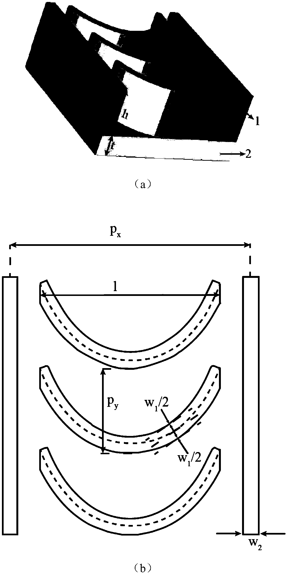
[0019] Such as figure 1 As shown, a high-efficiency metasurface device based on a dielectric continuous structure to realize large-field imaging includes a dielectric grating structure 1 , a dielectric substrate 2 and a dielectric continuous structure 3 . The thickness of the dielectric grating structure 1 is h, and the radial period is P x , the tangential period is P y , with a width of w 2 ; The thickness of the dielectric substrate 2 is t; the radial span of the dielectric continuous structure 3 is l, and the width is w 1 , the thickness is h.

[0020] Combined with the above structure, in...


PUM


Abstract

The invention provides a high-efficiency super-surface device for realizing large field of view imaging based on a dielectric continuous structure. The device comprises a dielectric grating structure(1), a dielectric substrate (2) and a dielectric continuous structure (3), and the monolithic imaging half field of view reaches 88 degrees. The continuous structure designed by the invention has theadvantages of high efficiency, large bandwidth and the like, also has angular insensitivity, and still has high efficiency under large-angle incidence. The scheme of the invention realizes large fieldof view imaging with characteristics of single piece, flat plate, light weight, thinness and integration.

Description

technical field [0001] The invention relates to the technical field of electromagnetic wave phase regulation, in particular to a high-efficiency metasurface device for realizing large-field imaging based on a continuous medium structure. Background technique [0002] With the development of photoelectric imaging technology, in order to obtain target image information with larger spatial range and more spatial details, the optical system is gradually developing in the direction of large field of view, light weight and even integration. Lightweight optical imaging systems with large fields of view have broad application prospects in military fields such as aerospace remote sensing, aerial reconnaissance, seekers, and space situational awareness. Typical design methods for large field of view imaging devices include the multi-element large field of view fisheye lens, which has a large number of lenses and a large length, making it difficult to develop towards light weight and i...

Claims


Application Information

Patent Timeline
Patent Type & Authority Applications(China)
IPC IPC(8): G02B5/18G02B5/30G02B27/00
CPCG02B5/1871G02B5/30G02B27/0012
Inventor 罗先刚蒲明博马晓亮张飞李雄
Owner INST OF OPTICS & ELECTRONICS - CHINESE ACAD OF SCI
Why Eureka
Try Eureka