Pneumatic method for separating mineral raw materials

A technology for mineral raw materials and raw materials, which is applied in solid separation, chemical instruments and methods, and separation of solids from solids by air flow. The effect of improving selectivity and improving performance

Active Publication Date: 2022-07-22
СТЕПАНЕНКО, АНДРЕЙ ИВАНОВИЧ
View PDF4 Cites 0 Cited by
  • Summary
  • Abstract
  • Description
  • Claims
  • Application Information

AI Technical Summary

Problems solved by technology

[0017] Second, an increase in the conveyor speed automatically leads to a change in the diluted fluidized bed layer and an increase in density near the rear wall of the vertical chamber (along the direction of conveyor movement), which disturbs the normal flow of particle motion in the pseudo-boiling layer ( because of increased density of the particles), which prevents particles of lower density from passing through it, i.e. this causes heavier particles to dislodge lighter particles and reduces the performance of the separation process

Method used


Image

  • Pneumatic method for separating mineral raw materials
  • Pneumatic method for separating mineral raw materials
  • Pneumatic method for separating mineral raw materials

Examples


Embodiment Construction

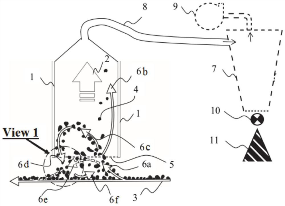
[0033] In order to understand the claimed method, first, let us consider the processes that take place in a split vertical chamber, as figure 1 As shown, the particles 4 of the raw material are separated and moved within the air-permeable belt conveyor 3 . The smallest fraction of particles is filtered by conveyor 3 and removed from the particle separation area (the process of filtering and conditionally removing spilled particles by conveyor 3 is not shown schematically). Next, the particles 4 moving on the conveyor 3 reach the entry area of ​​the separating vertical chamber, defined by the wall 1 , where the particles 4 and the air flow 2 are sucked through its open bottom opening 5 . Thus, in the area adjacent to the open bottom 5 of the separating vertical chamber, a vortex of moving particles 6a-6e occurs, formed by the simultaneous impact of the particles 4 by horizontal energy, which is in line with their movement on the belt conveyor 3 and The vertical lift force cre...


PUM


Abstract

The present invention relates to the field of separation of mineral feedstocks and can be used to produce mobile separation plants for processing and sorting feedstocks according to fractions in any weather conditions, including ambient air temperatures of -50 to +50°C. What is claimed is a pneumatic method for separating mineral feedstock comprising: placing the feedstock to be separated on a gas permeable surface extending through a separation chamber, wherein an ascending gas flow lifts light fractions from the gas permeable surface, the latter is in the form of a conveyor passing under the bottom of the separation chamber, wherein, by selecting the air flow rate, a diluted fluidized bed is formed of particles of a specific density, wherein the less dense particles are transferred from the separation chamber by an upward flow of air Unhindered entry and passage to the gravity deposition chamber, characterized in that said separation chamber is inclined towards the conveyor plane, while its bottom is parallel to the conveyor plane, and is formed by the longitudinal walls of the separation chamber and its bottom. Acute angles point in the direction of movement of the conveyor.

Description

technical field [0001] The present invention relates to the field of separation of mineral raw materials and can be used for the production of mobile separation plants which treat and sort the raw materials according to their elements and can be used in any weather conditions, including at temperatures of -50 to +50°C. Background technique [0002] It is well known that one of the main methods of separating ores, coal, non-metallic materials is a specific density separation method (ie gravity method). The decline in the quality of the raw materials extracted and the increased quality requirements for concentrates for further processing by power engineering, metallurgical and chemical enterprises have greatly increased the requirements for the efficiency of the raw material separation methods employed. [0003] Similarly, it is known that large amounts of mineral waste have accumulated during the operation of separation plants and metallurgical processing plants. These waste...

Claims


Application Information

Patent Timeline
Patent Type & Authority Patents(China)
IPC IPC(8): B07B4/08
CPCB07B4/08
Inventor 安德烈·伊万诺维奇·斯捷潘年科
Owner СТЕПАНЕНКО, АНДРЕЙ ИВАНОВИЧ
Why Eureka
Try Eureka