Eureka AIR delivers breakthrough ideas for toughest innovation challenges, trusted by R&D personnel around the world.

Power supply circuit for filament of high-power electronic tube

A technology of power supply circuit and electron tube, applied in the direction of output power conversion device, DC power input conversion to DC power output, electrical components, etc., can solve the problem of limited adjustment range and achieve effective control

Inactive Publication Date: 2003-01-29
马廷和
View PDF1 Cites 0 Cited by
  • Summary
  • Abstract
  • Description
  • Claims
  • Application Information

AI Technical Summary

Problems solved by technology

However, the inventor believes that the method of connecting the "error amplifier non-inverting input terminal" makes its control circuit only change the pulse width of the PWM device, and the adjustment range is extremely limited

Method used


Image

  • Power supply circuit for filament of high-power electronic tube
  • Power supply circuit for filament of high-power electronic tube
  • Power supply circuit for filament of high-power electronic tube

Examples


Embodiment 1

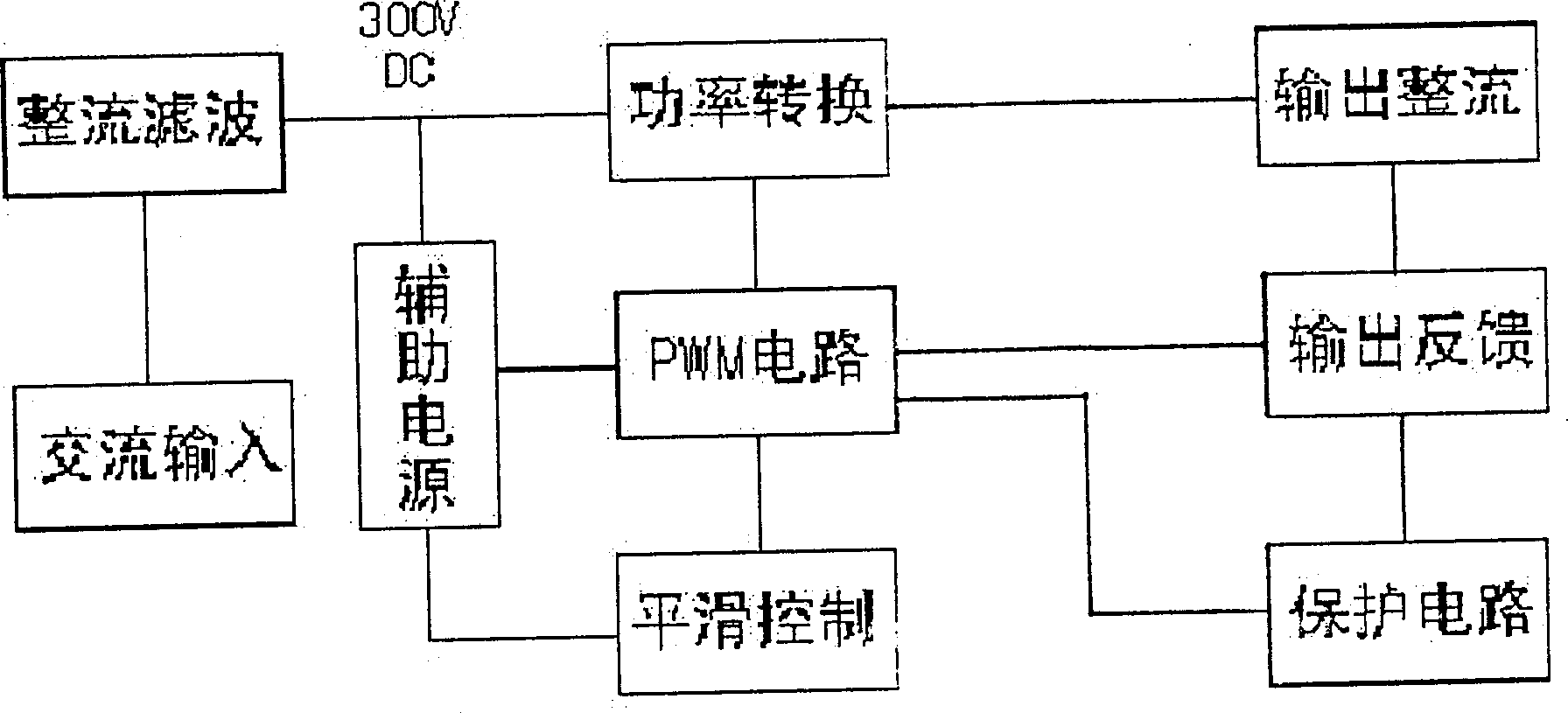
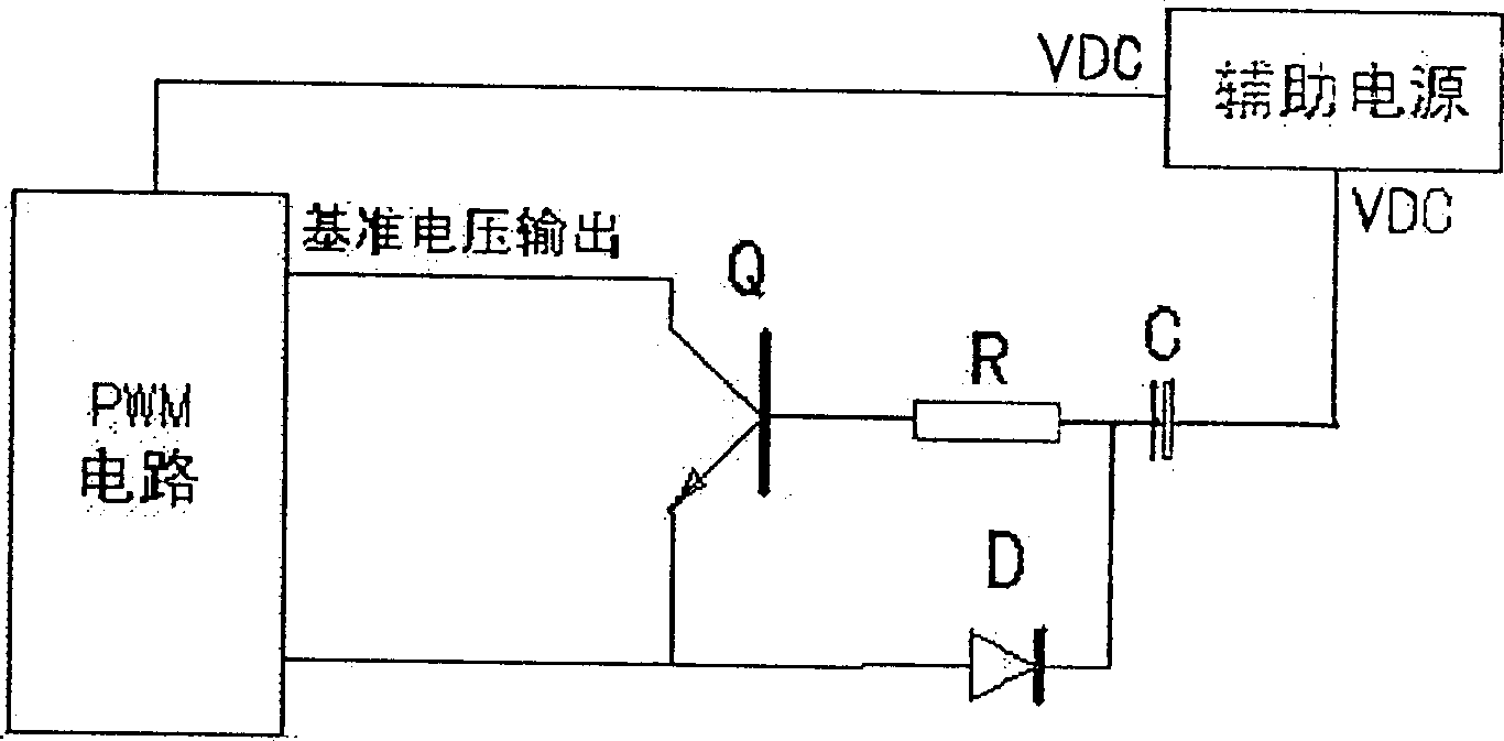
[0022] See attached figure 1 , figure 2 , the present invention adopts the switch regulated power supply with pulse width modulation circuit PWM as the control circuit, and provides a smooth control circuit for the switch regulated power supply that can smoothly raise its reference voltage to the rated value from zero.

[0023] Such as figure 1 As shown, the switching regulated power supply in this embodiment takes the AC power supply as the AC input, directly rectifies and filters to obtain a 300V DC high voltage, and then sends it out in two ways, one way provides power for power conversion, and the other way generates 12-25V auxiliary power supply. As a working power supply for other unit circuits such as pulse width modulation. A series of output pulse voltages with adjustable pulse width are generated in the pulse width modulation circuit, and the voltage is fed back to the output terminal of the power tube to control the power tube to be in the on or off state, and th...

Embodiment 2

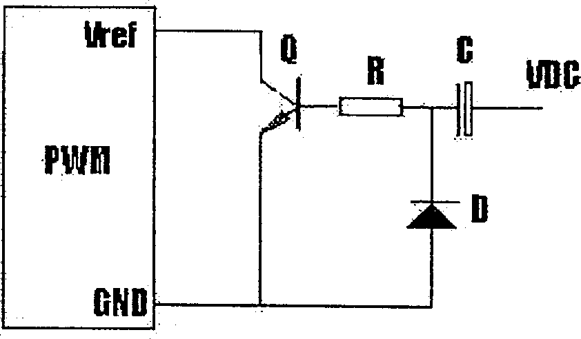
[0029] see Figure 4 , Image 6 The difference from the above-mentioned embodiment 1 is that in this embodiment, the collector of the transistor Q is connected to the reference voltage output terminal of the voltage comparator of the XX1525 chip, which is pin 1, and the emitter is grounded. The circuit is especially suitable for the reference voltage input terminal of the voltage comparator to have external pins on the chip.


PUM


Abstract

A power supply circuit for the filament of high-power electronic tube features that it uses a voltage-stabilized switching power supply controlled by PWM circuit and a smoothing controller for raising up its reference voltage from zero to rated value smoothly. It can make the voltage smoothly applied to the filament until a steady value, preventing current shock to elongate the service life of electronic tube by more than 5 times.

Description

Technical field: [0001] The present invention relates to power circuits. More specifically, it is a power supply circuit for high-power electronic tube filaments. Background technique: [0002] The voltage and current applied to the cathode of the electron tube are necessary conditions for the normal operation of the electron tube. It can make the cathode temperature of the electron tube reach thousands of degrees. Since the voltage applied to the filament directly affects the life of the electron tube, it must have a certain degree of stability and accuracy. However, various power supply circuits in the prior art have no high-precision voltage stabilizing measures, and there are surge current impacts, etc., which not only greatly affect the service life of the electron tube, but also have low efficiency and high energy consumption. [0003] In the publication specification of the invention patent application whose publication number is CN1069348A, a kind of "switching pow...

Claims


Application Information

Patent Timeline
Patent Type & Authority Patents(China)
IPC IPC(8): G05F1/46H02M3/00
Inventor 马廷和
Owner 马廷和
Why Eureka
Eureka Blog
Learn More