
Thermal protection system and method for gas turbine components

A gas turbine, thermal protection technology, applied in the direction of engine components, superimposed layer plating, blade support elements, etc., can solve problems such as ceramic parts or joint failures, achieve stress relief levels, heat flux reduction, cooling Effect of Air Consumption Reduction

Pending Publication Date: 2019-07-19
ANSALDO ENERGIA IP UK LTD
View PDF19 Cites 1 Cited by
  • Summary
  • Abstract
  • Description
  • Claims
  • Application Information

AI Technical Summary

Problems solved by technology

[0015] In general, joining ceramic materials to metallic materials often results in stress and, in many cases, failure of the ceramic part or joint

Method used


Image

  • Thermal protection system and method for gas turbine components
  • Thermal protection system and method for gas turbine components
  • Thermal protection system and method for gas turbine components

Examples


Embodiment Construction

[0042] see figure 1 , a gas turbine 1 (not shown in its entirety) has at least one component 2 provided with a thermal protection system 3 .

[0043] For example, the member 2 is a blade 2a or a blade support portion 2b. However, it should be understood that other components 2 of the gas turbine 1 may require thermal protection and thus may be provided with the thermal protection system 3 of the present invention.

[0044] The thermal protection system 3 comprises a high temperature resistant ceramic element 4 coupled to the metal wall 5 of the component 2 .

[0045] The component 2 or at least the wall 5 is made of metallic material.

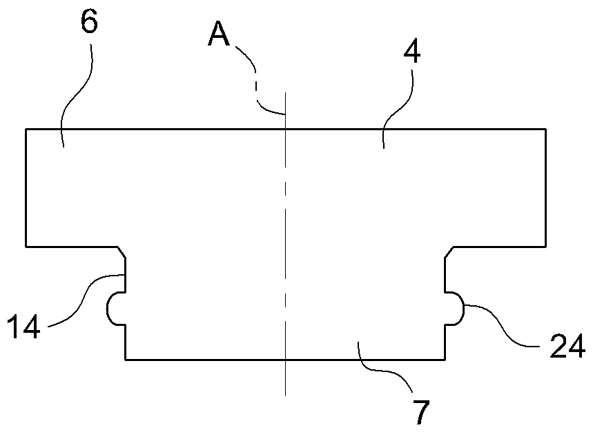
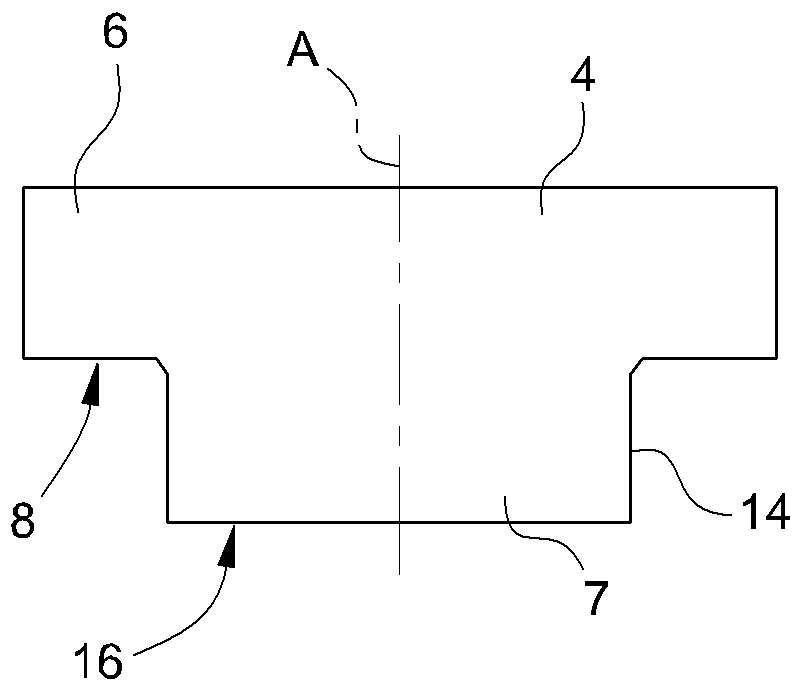
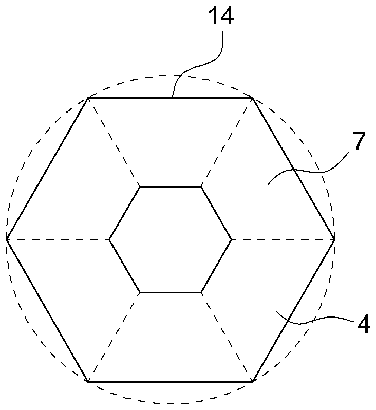
[0046] see also figure 2 and image 3 The ceramic element 4 , for example in the form of a covering tile, comprises a main body 6 and a root portion 7 protruding from a bottom surface 8 of the main body 6 .

[0047] Preferably, the ceramic element 4 is a single piece formed by the body 6 and the root portion 7 and made of ceramic materia...


PUM


Abstract

A thermal protection system (3) for gas turbine components comprises a component (2) of a gas turbine (1) and a high temperature resistant ceramic element (4) which is coupled to a wall (5) of the component (2); the ceramic element (4) comprises at least a root portion (7) matching and engaging a hollow seat (10) formed in the wall (5) of the component (2); the root portion (7) is a brazed-in or cast-in or cemented-in root portion (7) so that the root portion (7) and the wall (5) of the component (2) are mechanically interlocked thus defining a shape-coupling (11), and are also connected by abrazed or cast or cemented joint (21).

Description

[0001] Cross References to Related Applications [0002] This application claims priority from European Patent Application No. 17210005.9 filed 22 December 2017, the entire disclosure of which is incorporated herein by reference. technical field [0003] The present invention relates to a thermal protection system and method for gas turbine components. Background technique [0004] In the field of gas turbines, it is well known that there is a need for effective thermal protection of components / surfaces that operate at very high temperatures and are also exposed to particularly harsh environments, since components experience high levels of The stress is not only thermal stress, but also corrosion and mechanical stress. [0005] Therefore, there is an urgent need for high-temperature and efficient thermal protection systems (TPS). [0006] The main types of TPS currently available for thermal protection of gas turbine components are: [0007] 1) TBC (Thermal Barrier Coati...

Claims


Application Information

Patent Timeline
IPC IPC(8): F01D25/08F01D5/30F01D9/02
CPCF01D25/08F01D5/3092F01D9/02F01D25/005B23K1/0018B23K35/0222C04B37/02C23C28/30C23C28/345C23C28/3455F01D5/08F01D5/28F01D5/284F05D2230/237C04B37/021C04B2237/38C04B2237/343C04B2237/348C04B37/026C04B2237/84F05D2260/36F05D2250/21F05D2250/232F05D2250/292
Inventor H-P.博斯曼J.克鲁科尔斯H.布兰多L.博达尼克R.科恩克
Owner ANSALDO ENERGIA IP UK LTD
Learn More