Milling cutter dynamic cutting force model construction and verification method under vibration effect

A verification method and cutting force technology, applied in special data processing applications, instruments, electrical digital data processing, etc., can solve problems such as only considering the impact of cutting force and milling vibration, and achieve the effect of ensuring reliability

Active Publication Date: 2019-07-19
HARBIN UNIV OF SCI & TECH
View PDF5 Cites 5 Cited by
  • Summary
  • Abstract
  • Description
  • Claims
  • Application Information

AI Technical Summary

Problems solved by technology

[0006] The purpose of this invention is to provide a dynamic cutting force model construction and verification method for milling cutters under th

Method used


Image

  • Milling cutter dynamic cutting force model construction and verification method under vibration effect
  • Milling cutter dynamic cutting force model construction and verification method under vibration effect
  • Milling cutter dynamic cutting force model construction and verification method under vibration effect

Examples


specific Embodiment approach 1

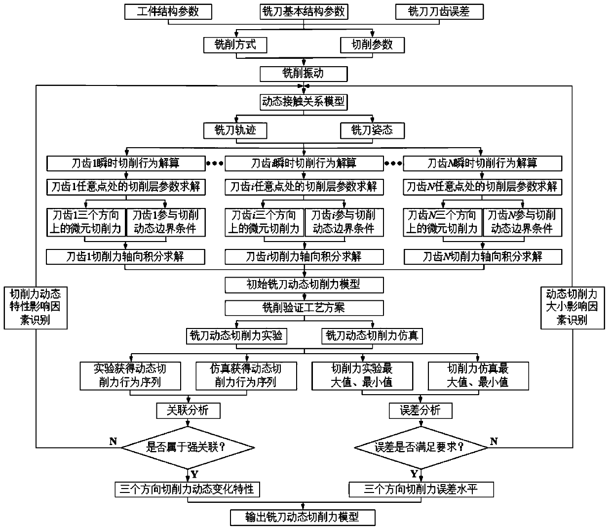
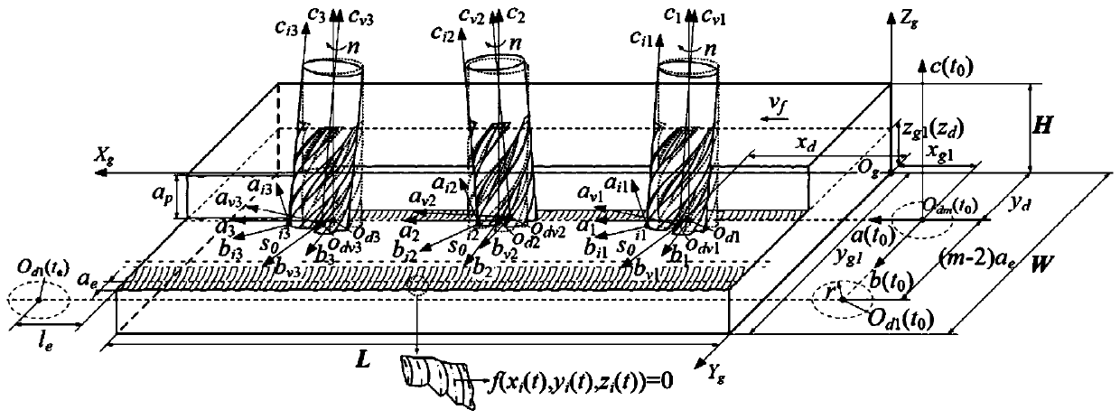
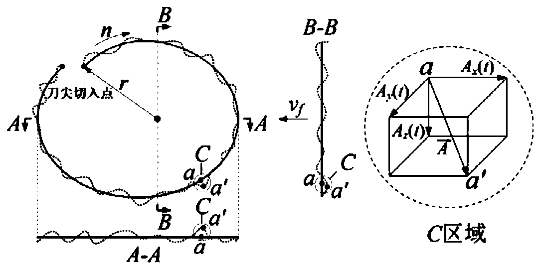
[0064] Specific implementation mode 1, a dynamic cutting force model construction and verification method for milling cutters under the action of vibration, such as figure 1 As shown, where N represents the number of teeth of the milling cutter, the process of milling titanium alloy by the end mill is analyzed, and the model of the instantaneous contact relationship of the milling cutter under the action of vibration is established; according to the contact relationship of the milling titanium alloy cutter, the actual cutting motion trajectory of the milling cutter is calculated and attitude; build a milling cutter structure model, divide the cutting edge into micro-elements, characterize the spatial position of the cutting edge, and determine the single-tooth cutting boundary conditions; according to the trajectory and attitude, establish the instantaneous cutting layer parameter model of the cutter tooth under the action of vibration, and construct the instantaneous cutting ed...

specific Embodiment approach 2

[0126] Vibration Variation Characteristics of Milling Titanium Alloy

[0127] (1) The experiment was carried out on a three-axis milling machining center (VDL-1000E), using the milling method of down milling, the spindle speed n was 1290r / min, and the feed rate was v f It is 573mm / min. Vibration is tested by DHDAS5922 dynamic signal test system.

[0128] Acquisition of vibration acceleration signals such as Figure 4 shown.

[0129] In the figure, T 1 , T 2 , T 3 and T 4 They are idling, initial stage of cut-in, smooth cutting and cut-out idling stage.

[0130] (2) Taking the vibration signal in the cutting speed direction obtained in the experiment as an example, use matlab to perform noise reduction processing on the vibration acceleration signal, and perform sine function fitting on the vibration acceleration signal after noise reduction, and the specific fitting results Such as Figure 5 and Figure 6 shown.

[0131] Equation fitting is performed on the vibratio...


PUM


Abstract

The invention discloses a milling cutter dynamic cutting force model construction and verification method under a vibration effect, which belongs to the technical field of milling cutters and aims tosolve the problems that the existing research on cutting force modeling cannot reveal the distribution and change characteristics of the cutter tooth milling infinitesimal instantaneous cutting force,cannot reveal the relation between cutter teeth and cutter teeth and cannot accurately reflect the dynamic change process of the cutting force. The method comprises the steps of a solving the instantaneous cutting behavior of the milling cutter; b, solving a single-tooth cutting boundary condition under the vibration effect; step c, establishing and calculating a milling cutter tooth instantaneous cutting layer parameter model; d, establishing an instantaneous cutting force model of the cutter teeth of the milling cutter and solving; and e, completing construction and verification of the milling cutter dynamic cutting force model. According to the dynamic cutting force model construction and verification method for the milling cutter under the vibration effect, the dynamic cutting force model capable of accurately reflecting the dynamic change of the cutting force in the cutting process can be constructed, and triple verification is carried out on the dynamic cutting force predictionmodel.

Description

technical field [0001] The invention relates to a method for constructing and verifying a dynamic cutting force model of a milling cutter, in particular to a method for constructing and verifying a dynamic cutting force model of a milling cutter under the action of vibration, and belongs to the technical field of milling cutters. Background technique [0002] Vibration during the cutting process will lead to continuous changes in cutting behavior, resulting in constant changes in cutting layer parameters, resulting in frequent changes in cutting force, resulting in changes in cutting load during milling, and ultimately causing tool wear and reduced surface quality. At the same time, the vibration interacts with the cutting force, and as the cutting progresses, this interaction continues to strengthen, eventually leading to cutting instability. In order to deeply reveal the interaction relationship between vibration and cutting force, control milling stability, improve workpi...

Claims


Application Information

Patent Timeline
IPC IPC(8): G06F17/50
CPCG06F30/17G06F2119/06G06F30/20
Inventor 姜彬张庭政赵培轶赵俊峰
Owner HARBIN UNIV OF SCI & TECH
Why Eureka
Try Eureka