
Sparse linear array optimization arrangement method under geographic constraint

A linear array and geographic technology, applied in the field of sparse linear array optimization, can solve the problems of increased side lobe level of the pattern, slow convergence speed of the PSO algorithm, and inability to achieve in-phase superposition.

Active Publication Date: 2019-07-19
UNIV OF ELECTRONICS SCI & TECH OF CHINA
View PDF4 Cites 9 Cited by
  • Summary
  • Abstract
  • Description
  • Claims
  • Application Information

AI Technical Summary

Problems solved by technology

Sparse array elements are placed irregularly, and the spatial sampling is non-uniform sampling. The array cannot achieve in-phase superposition on the far-field grating lobes, and the energy of the grating lobes can be effectively pressed into the side lobes, so the grating lobes can be eliminated, but it will bring Incoming pattern side lobe level increased
[0003] In order to overcome the shortcoming of the high sidelobe of the sparse array pattern, there is a sparse linear array optimization method, which considers the sum of the peak sidelobe levels (PSL) of the pattern under all scanning angles in the observation space, and takes it as the optimized The objective function, and then add array element size constraints and geographical constraints to the fixed aperture array element, and use the particle swarm optimization (PSO) algorithm to minimize the objective function value to solve the corresponding array element position
However, this method takes the sum of the peak sidelobe levels of all scanning angles as the optimization objective function, which cannot guarantee that the peak sidelobe levels of each scanning direction will reach the minimum; at the same time, the PSO algorithm has a slow convergence speed and is easy to fall into a local optimal solution

Method used


Image

  • Sparse linear array optimization arrangement method under geographic constraint
  • Sparse linear array optimization arrangement method under geographic constraint
  • Sparse linear array optimization arrangement method under geographic constraint

Examples


Embodiment Construction

[0076] Embodiments of the present invention will be further described below in conjunction with the accompanying drawings.

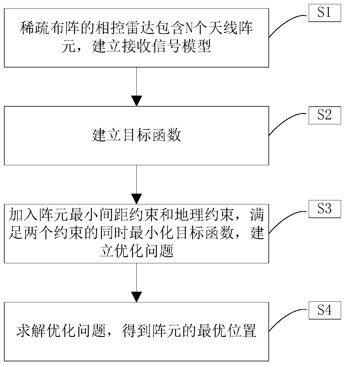
[0077] see figure 1 , a sparse linear array optimization array method proposed by the present invention under geographical constraints, realized by the following steps:

[0078] S1. The sparsely arranged phased array radar includes signals of N antenna elements, and a receiving signal model is established.

[0079] In this embodiment, there is a sparse array phased array radar with N array elements, and the N array elements are all on the x-axis, and the positions of the array elements are respectively d 0 , d 1 ,...,d N-1 , and the position satisfies |d N-1 -d 0 |>λN / 2,x n (t) is the signal received by the nth array element, x n (t) has a phase offset relative to the reference signal s(t) Expressed as

[0080]

[0081] Among them, n=1,2,...,N, θ 0 Represents the scan angle of the far field; define g(θ,t) as the joint x expressed based on t...


PUM


Abstract

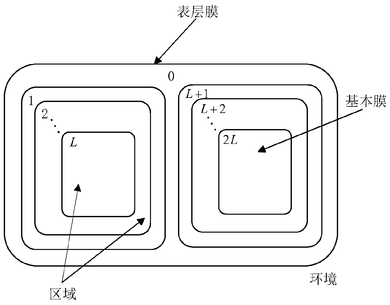
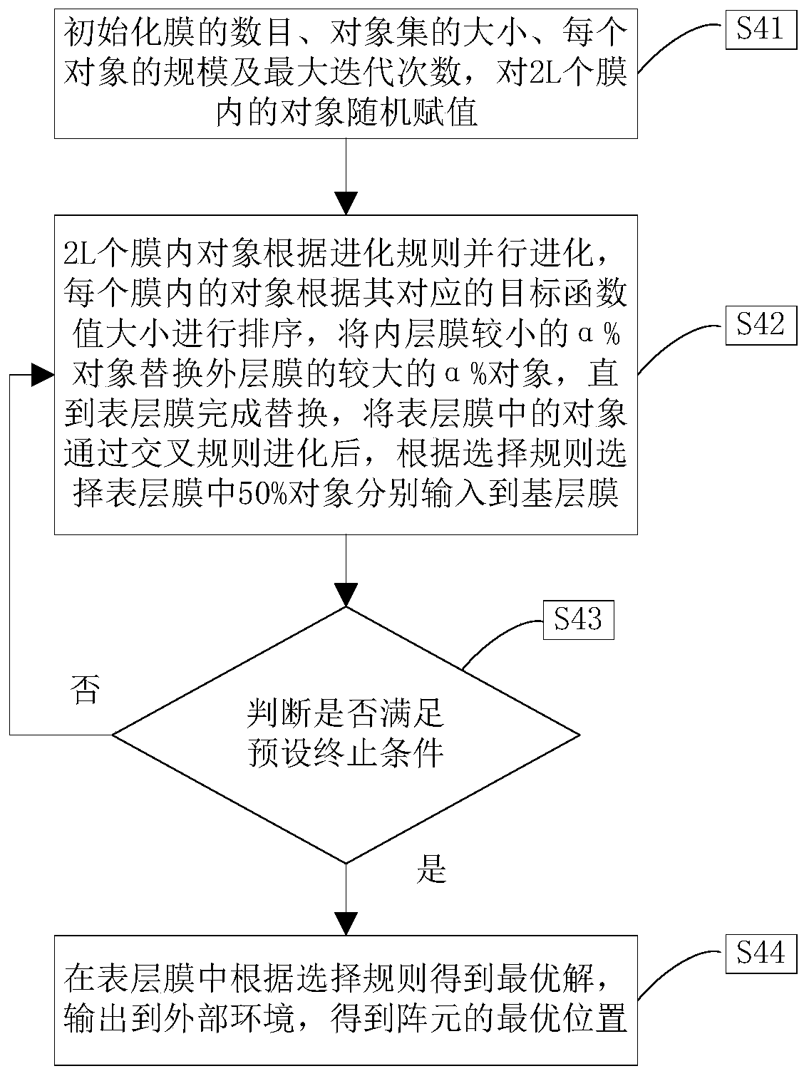
The invention provides a sparse linear array optimization arrangement method under geographic constraint, and belongs to the field of array signal processing. The invention aims to solve the problem of sparse linear array arrangement to establish a sparse linear array transmission signal model, establishes an objective function by taking the peak value side lobe level of the antenna directional diagram as an optimization standard, consides the actual condition in the array, and adds an antenna minimum spacing constraint and a geographic constraint to ensure that all the scanning angle peak value side lobe levels in the observation airspace are optimized to the minimum; compared with an original algorithm for solving the sparse linear array optimization problem, the membrane algorithm (MAPS) based on the P system has the advantages of being higher in convergence speed and good in convergence effect.

Description

technical field [0001] The invention belongs to the field of array signal processing, in particular to a sparse linear array optimization array method under geographical constraints. Background technique [0002] In the optimal layout of sparse linear array (Sparse Linear Array, SLA), the positions of the array elements are randomly placed according to a certain distribution. Compared with the uniform linear array, the aperture of the array is increased, the scanning beam is narrowed, the directionality is enhanced, and the spatial resolution is improved. , the mutual coupling effect between array elements is weakened, and grating lobes can be avoided in the pattern, so the optimal layout of sparse arrays has been extensively studied. Sparse array elements are placed irregularly, and the spatial sampling is non-uniform sampling. The array cannot achieve in-phase superposition on the far-field grating lobes, and the energy of the grating lobes can be effectively pressed into ...

Claims


Application Information

Patent Timeline
Patent Type & Authority Applications(China)
IPC IPC(8): G06F17/50H04W4/021
CPCH04W4/021G06F30/18G06F30/20
Inventor 杨晓波干娜杨婧赖淦崔国龙郭世盛孔令讲张天贤
Owner UNIV OF ELECTRONICS SCI & TECH OF CHINA
Learn More