CAN bus wake-up circuit

A technology of CAN bus and wake-up circuit, which is applied in the field of CAN network communication, can solve problems such as slow response time, complex logic, and high chip price, and achieve the effects of low cost, simple circuit structure, and fast wake-up speed

Active Publication Date: 2019-07-19
AUTOCORE INTELLIGENT TECH NANJING CO LTD
View PDF8 Cites 3 Cited by
  • Summary
  • Abstract
  • Description
  • Claims
  • Application Information

AI Technical Summary

Problems solved by technology

This kind of technical software logic is complex, the response time is slow, and the chip with CAN wake-up function is expensive, which is not conducive to cost control

Method used


Image

  • CAN bus wake-up circuit
  • CAN bus wake-up circuit
  • CAN bus wake-up circuit

Examples


Embodiment 1

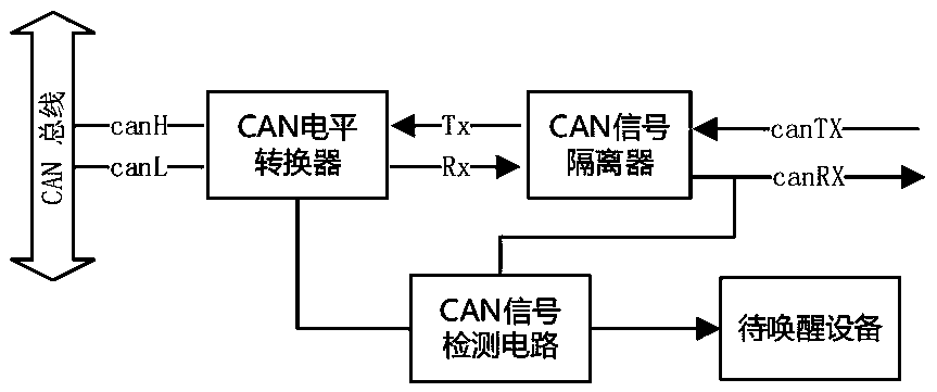
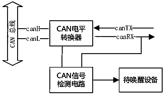
[0019] A preferred embodiment of the present invention is figure 1 As shown, the CAN bus wake-up circuit includes a CAN signal isolator U1, a CAN level converter U2 and a CAN signal detection circuit; the output terminal of the CAN signal detection circuit is connected to the device to be woken up, and the device to be woken up passes through the CAN signal isolator U1 and CAN level converter U2 is connected with CAN bus.

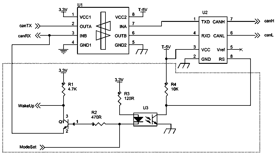
[0020] Such as figure 2 , the CAN signal detection circuit includes an optocoupler U3; the collector C of the phototransistor at the output end of the optocoupler U3 is connected to the first DC source through a resistor R4, the output terminal of the optocoupler U3 is connected to the photosensitive triode, and the emitter of the phototransistor E is grounded, and the collector C of the phototransistor at the output end of the optocoupler U3 is also connected to the RS end of the CAN level converter U2; the anode of the photodiode at the input end of the...


PUM


Abstract

The invention relates to a CAN bus wake-up circuit which comprises a CAN signal isolator, a CAN level converter and a CAN signal detection circuit. The first input end of the CAN signal detection circuit is connected with a working mode setting signal of the wake-up circuit and is used for setting whether the wake-up circuit is in a normal mode or a sleep mode; and the second input end of the CANsignal detection circuit is connected to the CAN signal receiving end and is used for detecting the signal change on the CAN bus. The circuit has the advantages of being simple in structure, high in awakening speed, low in cost and the like.

Description

technical field [0001] The invention relates to a CAN bus wake-up circuit, which belongs to the technical field of CAN network communication. Background technique [0002] In recent years, with the continuous development of the automobile industry, the functions of automobiles have become more and more abundant and powerful, especially the advanced auxiliary driving functions, which can effectively help drivers reduce the occurrence of traffic accidents. The means to achieve advanced assisted driving is to continuously increase various sensors and ECUs. As the number of sensors and ECUs continues to increase, although the functions of the car are enriched, the problem is that the static power consumption of the whole vehicle continues to increase. Before the battery technology has achieved a qualitative breakthrough, in order to reduce the static power consumption of the whole vehicle, it is necessary The on-board electronic equipment can quickly enter the dormant state to ...

Claims


Application Information

Patent Timeline
IPC IPC(8): H04L12/40B60R16/02
CPCB60R16/02H04L12/40039H04L2012/40215H04L2012/40273
Inventor 王振华陈诚张旸
Owner AUTOCORE INTELLIGENT TECH NANJING CO LTD
Why Eureka
Try Eureka