Laboratory waste gas exhausting system and treatment method
A laboratory and waste gas technology, which is applied in the field of waste gas treatment and laboratory design, can solve the problems of low energy consumption and small investment, and achieve the effects of saving investment, simple equipment, improving adsorption efficiency and service life
- Summary
- Abstract
- Description
- Claims
- Application Information
AI Technical Summary
Problems solved by technology
Method used
Image


Examples
Embodiment
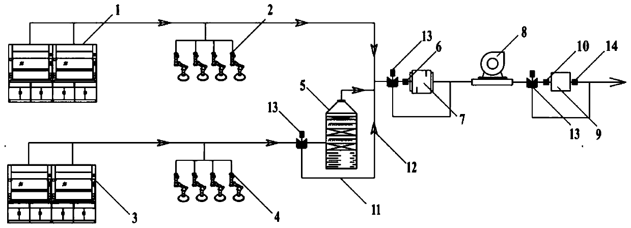
[0038] This embodiment provides a laboratory waste gas exhaust system, such as figure 1As shown, it includes two organic fume hoods 1, two inorganic fume hoods 3, four organic exhaust arms 2, four inorganic exhaust hoods 4, spray acid removal device 5, dehumidification device 7, frequency conversion centrifugal fan 8 and activated carbon adsorption Each of the devices 9; each organic fume hood 1 and each organic exhaust arm 2 are connected in parallel with air ducts, and then connected to the dehumidification device 7; The tubes are connected in parallel, first connected in series with the spray deacidification device 5, and then connected with the dehumidification device 7, the dehumidification device 7, the frequency conversion centrifugal fan 8 and the activated carbon adsorption device 9 are connected in sequence.
[0039] The spray acid removal device 5 is only connected to the side of the inorganic waste gas. When the spray acid removal device 5 does not receive the sign...
experiment example 1
[0057] In this experimental example, the situation where only the inorganic exhaust hood and the inorganic fume hood are opened is simulated. Start the spray deacidification device and dehumidification device at the same time, open some inorganic fume hoods and exhaust hoods, manually open the spray deacidification device, and automatically open the dehumidification device, without touching the activated carbon adsorption device, and calculate the power requirements of the centrifugal fan.
[0058] This experiment is based on the working conditions of 2 inorganic laboratories with 1 fume hood and 2 inorganic exhaust hoods (that is, a total of 2 fume hoods and 4 inorganic exhaust hoods), where the diameter and length of the ventilation pipes are simply assumed: The air volume of the 1200L fume hood is 1500m3 / h, and the total air volume of the inorganic fume hood is 3000m 3 / h; the air volume of the inorganic exhaust hood is 600m 3 / h, the wind speed at the cover mouth is 2m 3...
experiment example 2
[0060] This experimental example simulates the situation where only the organic exhaust arm and the organic fume hood are opened, the dehumidification device is not turned on, and the activated carbon adsorption device is turned on, and the power requirement of the centrifugal fan is calculated.
[0061] According to the working conditions of 2 organic laboratories with 1 fume hood and 2 organic exhaust arms (that is, a total of 2 fume hoods and 4 organic exhaust arms work), the diameter and length of the ventilation pipe are simply assumed: fume hood 1200L exhaust air volume is 1500m 3 / h, the total air volume of the organic fume hood is 3000m 3 / h; the air volume of the organic exhaust arm is 600m 3 / h, the wind speed at the cover mouth is 2m 3 / h, the total air volume of the organic exhaust arm is 2400m 3 / h; the organic exhaust area uses a 500*400mm rectangular exhaust pipe with a total length of 30m and a wind speed of 8m / s, which meets the exhaust requirements; the re...
PUM
| Property | Measurement | Unit |
|---|---|---|
| Resistance | aaaaa | aaaaa |
Abstract
Description
Claims
Application Information
 - R&D
- Intellectual Property
- Life Sciences
- Materials
- Tech Scout
- Unparalleled Data Quality
- Higher Quality Content
- 60% Fewer Hallucinations
Browse by: Latest US Patents, China's latest patents, Technical Efficacy Thesaurus, Application Domain, Technology Topic, Popular Technical Reports.
© 2025 PatSnap. All rights reserved.Legal|Privacy policy|Modern Slavery Act Transparency Statement|Sitemap|About US| Contact US: help@patsnap.com