
Dust removing mechanism used in machining process of foam milling machine

A milling machine processing and foaming technology, which is applied in metal processing machinery parts, metal processing equipment, manufacturing tools, etc., can solve the problems of polluted working environment and scattered debris, and achieve the effect of reliable operation, low cost and pollution elimination.

Pending Publication Date: 2019-07-23
吉林省诚鼎精密铸造有限公司
View PDF0 Cites 0 Cited by
  • Summary
  • Abstract
  • Description
  • Claims
  • Application Information

AI Technical Summary

Problems solved by technology

Overcome the deficiencies of the existing foam milling debris flying and polluting the working environment

Method used


Image

  • Dust removing mechanism used in machining process of foam milling machine
  • Dust removing mechanism used in machining process of foam milling machine
  • Dust removing mechanism used in machining process of foam milling machine

Examples


Embodiment Construction

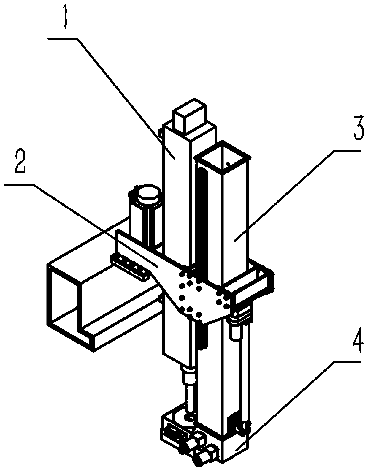
[0018] refer to figure 1 , The present invention is made up of mounting frame 2, lifting mechanism 3, dust suction crushing mechanism 4 and electric control system.

[0019] refer to figure 2 , wherein the mounting frame includes a left mounting plate 2-1 and a right mounting plate 2-2 fixed on the milling machine frame 1, a connecting plate 2-3 connecting the middle of the left and right mounting plates, and connecting the left and right mounting plates facing away from the end of the milling machine Electric push rod support plate 2-4, respectively installed in the left installation plate and the slide block 2-5 between the middle connecting plate 2-3 and the electric push rod support plate 2-4, in the inner side of the right installation plate,

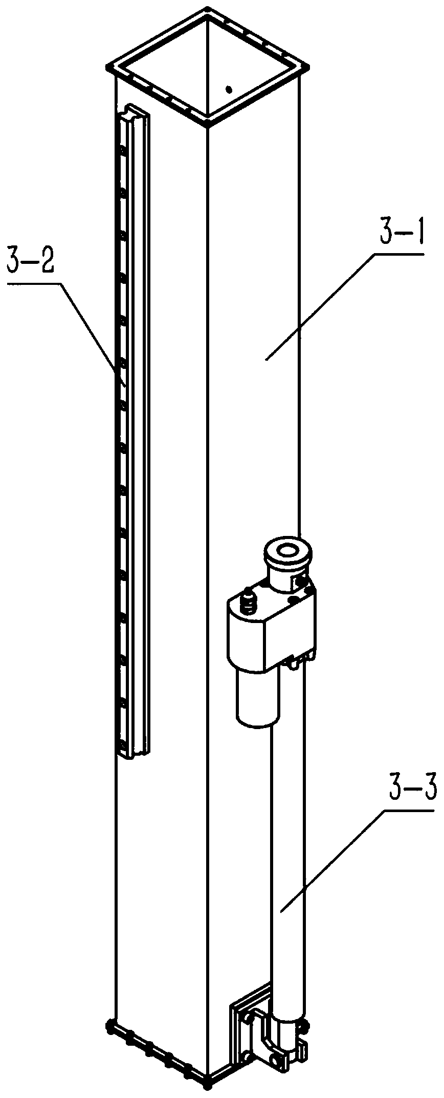
[0020] refer to image 3 , wherein the lifting mechanism includes a vertical cylindrical lifting rod 3-1, two linear slide rails 3-2 longitudinally fixed on both sides of the lifting rod, the slide rails cooperate with the slide...


PUM


Abstract

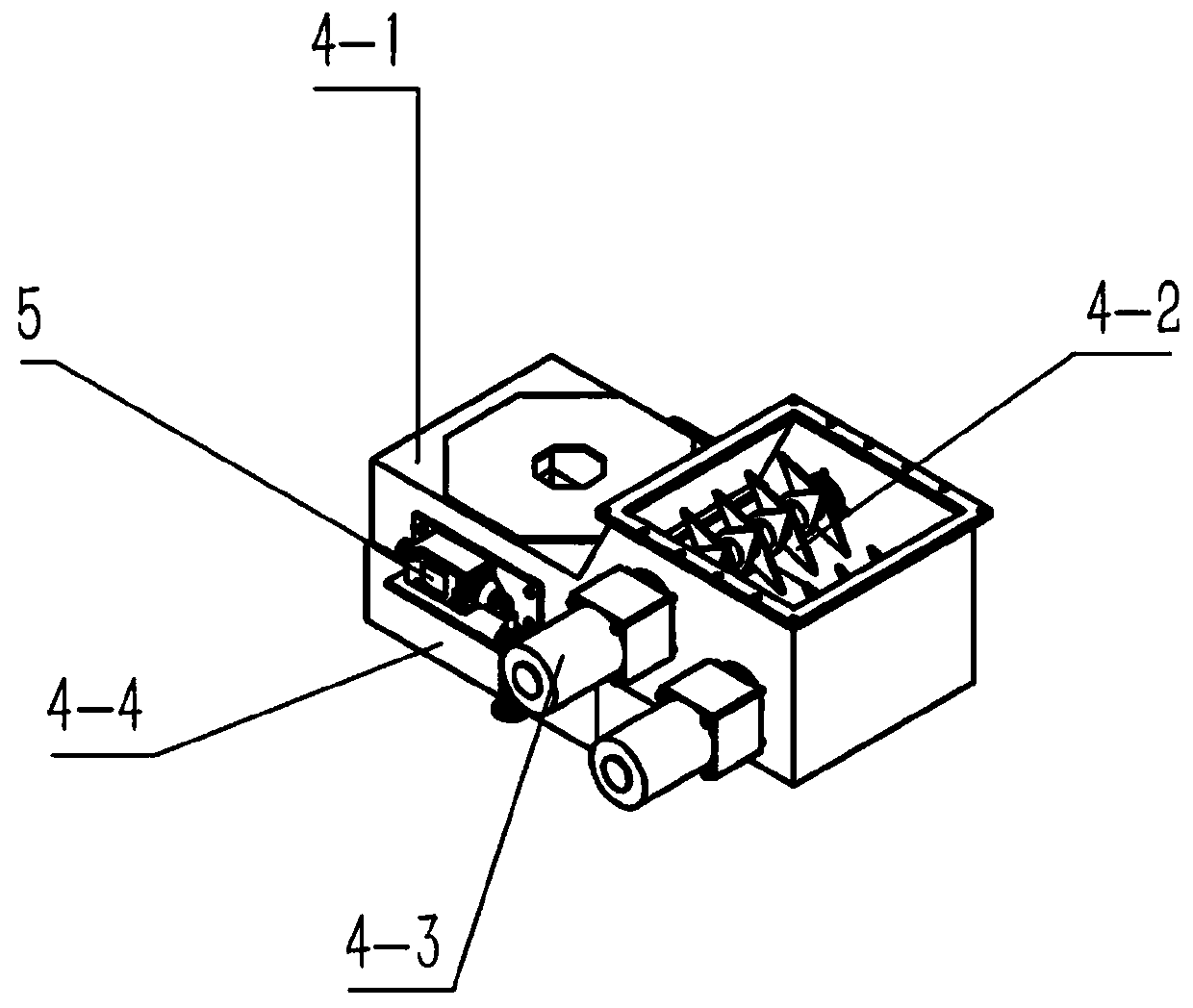
The invention discloses a dust removing mechanism used in the machining process of a foam milling machine. The dust removing mechanism is composed of an installation frame, a lifting mechanism, a dustsucking and breaking mechanism and an electric control system. The installation frame comprises a left installation plate, a right installation plate, a middle connecting plate, an electric push rodsupporting plate, and sliding blocks on the inner sides of the installation plates. The lifting mechanism comprises a lifting rod, a sliding rail on the lifting rod and an electric push rod which is disposed between the lifting rod and the installation frame. The dust sucking and breaking mechanism is composed of a dust sucking box, a breaking blade roller and dust stop bars which are disposed onthe periphery of a sucking opening of the dust sucking box. The dust sucking box is provided with a sucking-in cavity and a blade roller cavity. A blade roller is mounted in the blade roller cavity. Alifting rod is connected to the upper end of the blade roller cavity of the dust sucking box. The blade roller cavity communicates with an inner cavity of the lifting rod. An air inducing pipe is connected to the upper end of the lifting rod. The electric control system is composed of a PLC, a limit switch which is disposed at the lower end of the dust sucking box, and an electromagnetic switch.The dust removing mechanism has the positive effect that foam chippings which are milled off are collected around a milling blade tool and sucked away and flow smoothly in a channel. Environment pollution caused by EPS modeling is eliminated completely. The structure is simple, the construction cost is low, and running is reliable.

Description

[0001] Technical field: [0002] The invention belongs to the field of mechanical equipment, and in particular relates to a dust-absorbing and dust-proof mechanism in the process of forming EPS lost foam for casting. [0003] Background technique: [0004] Lost foam casting needs to use a foam model that is consistent with the size and shape of the casting. During the milling process of the foam model, a large amount of debris and dust will be generated, which will not only affect the environment and cause harm to human health, but also cause excessive dust. High risk of deflagration. At present, the common dust removal method is to use a dust collector to suck up the debris and dust near the milling machine after processing. This method can only be carried out when the equipment stops working, which reduces the production efficiency and cannot solve the problem of dust flying in the milling machine. [0005] Invention content: [0006] The object of the present invention is ...

Claims


Application Information

Patent Timeline
IPC IPC(8): B23Q11/00
CPCB23Q11/0046
Inventor 郑铎
Owner 吉林省诚鼎精密铸造有限公司
Learn More