Mold and production device for preparing foam sandwich panel

A foam sandwich panel and production equipment technology, which is applied in the field of sheet metal processing, can solve the problems of high requirements for metal powder uniformity and purity, the inability to effectively control the size of the surface metal sheet, and the inconsistency of the composition of the metal sheet and the sandwich layer. Guarantee the effect of foam metal foaming rate, high strength and high temperature

Active Publication Date: 2019-07-23
HEBEI UNIV OF TECH
View PDF7 Cites 4 Cited by
  • Summary
  • Abstract
  • Description
  • Claims
  • Application Information

AI Technical Summary

Problems solved by technology

The preparation of the sandwich plate with metal foam as the sandwich material is mainly through the following methods: one is to put the metal powder, the mixed powder of the metal powder and the foaming agent, and the metal powder into the mold in sequence, and heat it to generate heat by hot pressing or other methods. Foam to obtain metal foam sandwich panels, but the cost of the mold used in this method is relatively high, and the requirements for the uniformity and purity of the metal powder are relatively high
The second is to use hot pressing, rolling and other methods to obtain the composite material of metal plate-foam metal prefabricated plate and then foam it. However, because the surface of the foam metal has a porous structure, the interface bonding is not high, the life of the plate is reduced, and the surface cannot be damaged. The size of the metal sheet is effectively controlled, and the above two methods belong to the powder metallurgy method
The disadvantage of this preparation method is that the pipe needs to be cleaned before compounding, and it cannot be formed at one time. The process is more complicated, the cost is higher, and the composition of the metal plate and the sandwich layer is inconsistent, and it is easy to produce stress concentration during use and affect the service life.

Method used


Image

  • Mold and production device for preparing foam sandwich panel
  • Mold and production device for preparing foam sandwich panel
  • Mold and production device for preparing foam sandwich panel

Examples


Embodiment 1

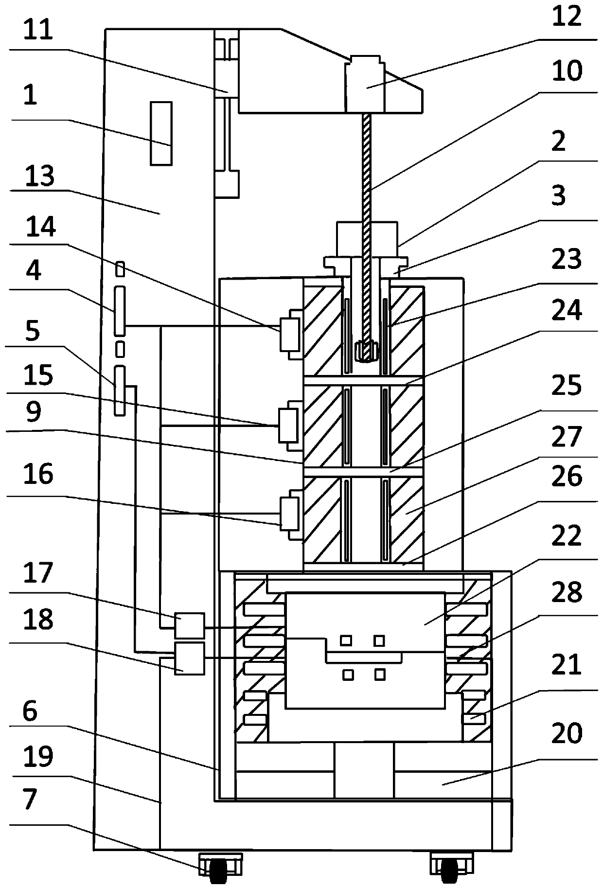
[0052] First, use the stirring paddle lifting device console 1 to lift the stirring paddle 10 out of the tube furnace cavity 27, raise the temperature of the first temperature zone of the tube furnace cavity 27 to 700°C, and raise the temperature of the second temperature zone to 600°C, The temperature of the third temperature zone is raised to 650°C, and the temperature of the box-type furnace cavity 28 is raised to 650°C. The protective gas is introduced into the box-type furnace cavity 28 through the protective gas inlet hole 8. At this time, the three baffles are pushed into the furnace.

[0053] Put 400g of the aluminum block into the first temperature zone of the tube furnace cavity 27 and keep it warm for 60 minutes. The liquid enters the second temperature zone. After the temperature of the molten aluminum is stabilized, add 0.4% calcium particle tackifier into the second temperature zone of the tube furnace cavity 27, stir for 4 minutes at a speed of 400r / min, and th...


PUM


Abstract

The invention discloses a mold and production device for preparing a foam sandwich panel. The mold comprises an ejection rod, a concave mold fixing plate, a concave mold, a convex mold and a convex mold fixing plate. The production device comprises a box furnace, a tube furnace, a stirring paddle, a stirring paddle lifting device, a speed adjustable motor, a first temperature zone temperature regulator, a second temperature zone temperature regulator, a third temperature zone temperature regulator, a box furnace temperature regulator, a cooled material flow rate regulator, a mold lifting device, a resistance wire, the mold, a first temperature zone baffle, a second temperature zone baffle and a third temperature zone baffle. One-time forming of the closed-cell foam metal sandwich panel isachieved by controlling the surface temperature and the internal temperature of melt on the basis of a melt foaming method; and production of sandwich panels with the same thickness and different foamlayer thicknesses is achieved by adjusting the cooled material flow rate, and production of sandwich panels of different thicknesses is achieved by adjusting the thickness of a gasket between the convex mold and the concave mold.

Description

technical field [0001] The invention relates to the field of plate processing, in particular to a mold and production equipment for preparing foam sandwich panels. Background technique [0002] Metal foam is a porous metal material that forms countless three-dimensional space network structures in the metal matrix. It has both metal properties and some special physical properties of non-metals. It is a structure-function integrated material with low density and high density. Porosity and other characteristics, its performance has high specific strength, energy absorption, electromagnetic shielding, structural damping performance, etc., it is an optional material for different structural instruments and devices, and has been widely used in the fields of automobiles, construction, aerospace, but metal foam At the same time, there are some shortcomings such as rough surface, low surface elastic modulus, and low assembly performance, which limit its application. [0003] Foam s...

Claims


Application Information

Patent Timeline
IPC IPC(8): C22C1/08
CPCC22C1/08C22C1/086
Inventor 夏兴川彭远祎张子晨杨东辉丁俭陈学广赵彦明
Owner HEBEI UNIV OF TECH
Why Eureka
Try Eureka