Fabricated type building automatic grouting equipment and method

A building automation and assembly technology, applied in the direction of buildings, building components, building reinforcements, etc., can solve the problems affecting the fluidity of grouting materials, low degree of automation, overturning of pipes and grouting funnels, etc., to improve convenience and automation , reduce personnel demand, and control the effect of timeliness

Pending Publication Date: 2019-07-23
CHINA METALLURGICAL CONSTR ENG GRP
View PDF10 Cites 15 Cited by
  • Summary
  • Abstract
  • Description
  • Claims
  • Application Information

AI Technical Summary

Problems solved by technology

[0003] However, there is a problem 1: the automation degree of the current operation is relatively low, and the process of grouting and grouting requires observers to observe the height of the liquid level of the grouting material in the grouting funnel. The observer notifies the operator to turn off the grouting pump by shouting, and the grouting process needs to be repeated many times, resulting in inconvenient operation, a large demand for personnel, and the overflow and waste of grouting material may also be caused by the delayed stop of pumping
Problem 2: The gravity grouting pressure formed by the liquid level difference between the grouting funnel and the grouting material in the grouting sleeve is limited. Simply relying on this pressure may cause ineffective grouting due to the influence of the fluidity of the grouting material, resulting in local grouting in the grouting sleeve. Cavity, hidden quality problems, especially the current grouting operation, in order to improve efficiency, it is implemented in a separate warehouse. A separate warehouse area is about 1.5 meters long, and there are multiple grouting sleeves (usually 3-4) in a divided warehouse area. , according to the number of pre-embedded steel bars in the prefabricated shear wall), the bottom of each grouting sleeve in a sub-storage area passes through the connecting warehouse (it can be the vertical gap where the prefabricated shear wall is hoisted to the fixed building, or It can be prefabricated at the bottom of the prefabricated shear wall) and connected, and the surrounding is closed. When grouting, select a grouting sleeve in the compartment area to connect the grouting pipe and the grouting funnel, and the grouting material flows through the connected compartment to fill other grouting In the sleeve, the grouting material should be blocked when the grouting port and the grouting port of other grouting sleeves overflow. In this way, the process of grouting and grouting is aimed at multiple grouting sleeves in a sub-bin area, and the connected bins Internal unevenness and unclean fine stone particles will further affect the fluidity of the grouting material, thereby affecting the effect of relying solely on gravity grouting
Problem 3: The current grouting funnel is connected to the grouting outlet through a rigid pipe, and the focus is on the grouting outlet. The grouting funnel is gradually pumped in due to the grouting material, which often causes the pipe and the grouting funnel to overturn.
The existing inspection operation generally requires 3 people to carry out, one person pours the grouting material into the truncated cone circular mold, one person observes the flatness of the circular mold and whether the grouting material is flush with the top of the circular mold, and one person lifts the circular mold and measures the flow diameter with a ruler , the operation is relatively complicated, and the inspection process is completely manual. Whether it is visual flushness, measuring the diameter with a ruler, or manually pulling the levelness, height, and speed of the truncated cone die, there are human errors, so the fluidity inspection The results will affect the quality of the grout; and the fluidity will change with time and environmental changes, but the fluidity of the grouting material cannot be effectively monitored during the grouting process

Method used


Image

  • Fabricated type building automatic grouting equipment and method
  • Fabricated type building automatic grouting equipment and method
  • Fabricated type building automatic grouting equipment and method

Examples


Embodiment Construction

[0030] The specific implementation manners of the present invention will be further described in detail below in conjunction with the accompanying drawings.

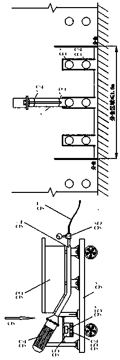
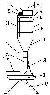
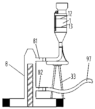
[0031] see Figure 1-3 , the prefabricated building automation grouting equipment of a specific embodiment, including a grouting machine 9 connected to the grouting port of the grouting sleeve for grouting and a grouting device connected to the grouting outlet of the grouting sleeve; Described grouting machine 9 comprises base frame 91, and described base frame 91 is provided with grouting pump 92, and the inlet end of described grouting pump 92 is connected with silo 93, and the outlet end is connected with grouting pipe 94 so as to communicate with the grouting sleeve. The grouting port; the grouting device includes a vertical grouting main cylinder 1, and the lower end of the grouting main cylinder 1 is provided with a communication pipe 2 so as to communicate with the grouting outlet of the grouting sleeve; the grout...


PUM


Abstract

The invention relates to fabricated type building automatic grouting equipment and method. The grouting equipment includes a grouting machine and a grout replenishing device; the grouting machine includes a base frame, a grouting pump is arranged on the base frame, a material bin is connected to the inlet end of the grouting pump, and a grouting pipeline is connected to the outlet end of the grouting pump for the outlet end of the grouting pump communicating with a grouting opening of a grouting sleeve conveniently; the grout replenishing device comprises a vertical grout replenishing main cylinder body, and a communicating pipe is arranged at the lower end of the grout replenishing main cylinder body for the lower end of the grout replenishing main cylinder body communicating with a groutoutlet of the grouting sleeve conveniently; a pressurizing mechanism is arranged at the upper end of the grout replenishing main cylinder body for providing additional grout replenishing pressure besides gravity grout replenishing during grout replenishing; the grout replenishing main cylinder body is further provided with a liquid level sensor for detecting the liquid level height of a groutingmaterial entering the grout replenishing main cylinder body; and the base frame is provided with a controller, and the controller is in signal connection with the liquid level sensor and is connectedwith the grouting pump in an electronic control mode for controlling starting and stopping of the grouting pump according to detection signals of the liquid level sensor. The fabricated type buildingautomatic grouting equipment and method have the effects that construction can be more convenient, and grouting quality can be effectively guaranteed.

Description

technical field [0001] The invention belongs to the technical field of fixed building foundation engineering components, and in particular relates to a prefabricated building automatic grouting equipment and a grouting method. Background technique [0002] During the construction of prefabricated buildings, the steel bars of prefabricated shear walls are often connected by grouting sleeves. The grouting material should be filled in the grouting sleeves and have a certain pressure to ensure the compactness. In order to ensure that the grouting material is filled in the grouting sleeve and has a certain pressure, it is more commonly used in the prior art to connect a grouting device at the grout outlet, such as CN109653506A, CN208347139U, CN109444389A, and CN208586820U. The basic idea is to use a Grouting funnel, the height of the grouting funnel is higher than the top of the grouting sleeve, and the bottom of the grouting funnel is connected to the grouting outlet of the grou...

Claims


Application Information

Patent Timeline
Patent Type & Authority Applications(China)
IPC IPC(8): E04G21/02E04C5/16
CPCE04G21/02E04C5/165
Inventor 陈晓磊魏奇科刘赫凯王勇勤杨虎翼朱晓霜刘博王振强
Owner CHINA METALLURGICAL CONSTR ENG GRP
Why Eureka
Try Eureka