
Spectral measurement device based on reflective random diffraction sheet and test method

A spectrum measurement and diffraction plate technology, applied in the field of spectrum measurement devices based on reflective random diffraction plates, can solve the problems of uncontrollable light scattering direction, low utilization rate of light energy of spectrometer, limited bandwidth of spectrometer, etc., and achieves convenient construction of optical path. Fast, simple and stable optical path structure, compact structure

Pending Publication Date: 2019-07-23
SUZHOU UNIV
View PDF0 Cites 0 Cited by
  • Summary
  • Abstract
  • Description
  • Claims
  • Application Information

AI Technical Summary

Problems solved by technology

[0003] Whether multimode fiber, disordered photonic chip or ground glass is used as the dispersion medium, the speckle pattern generated by different wavelengths passing through the disordered medium overlaps in space, which leads to the limitation of the bandwidth of the spectrometer, and because these disordered media will incident light Scattered in all directions, only a small part of the light can be received by the detector, so the utilization rate of light energy is generally very low
Although Wangpeng et al. used a broadband diffraction element as a dispersion medium to expand the bandwidth, the scattering direction of light is still uncontrollable, so the light energy utilization rate of the spectrometer is still relatively low

Method used


Image

  • Spectral measurement device based on reflective random diffraction sheet and test method
  • Spectral measurement device based on reflective random diffraction sheet and test method
  • Spectral measurement device based on reflective random diffraction sheet and test method

Examples


Embodiment Construction

[0038] The present invention will be further described below in conjunction with the accompanying drawings and specific embodiments, so that those skilled in the art can better understand the present invention and implement it, but the examples given are not intended to limit the present invention.

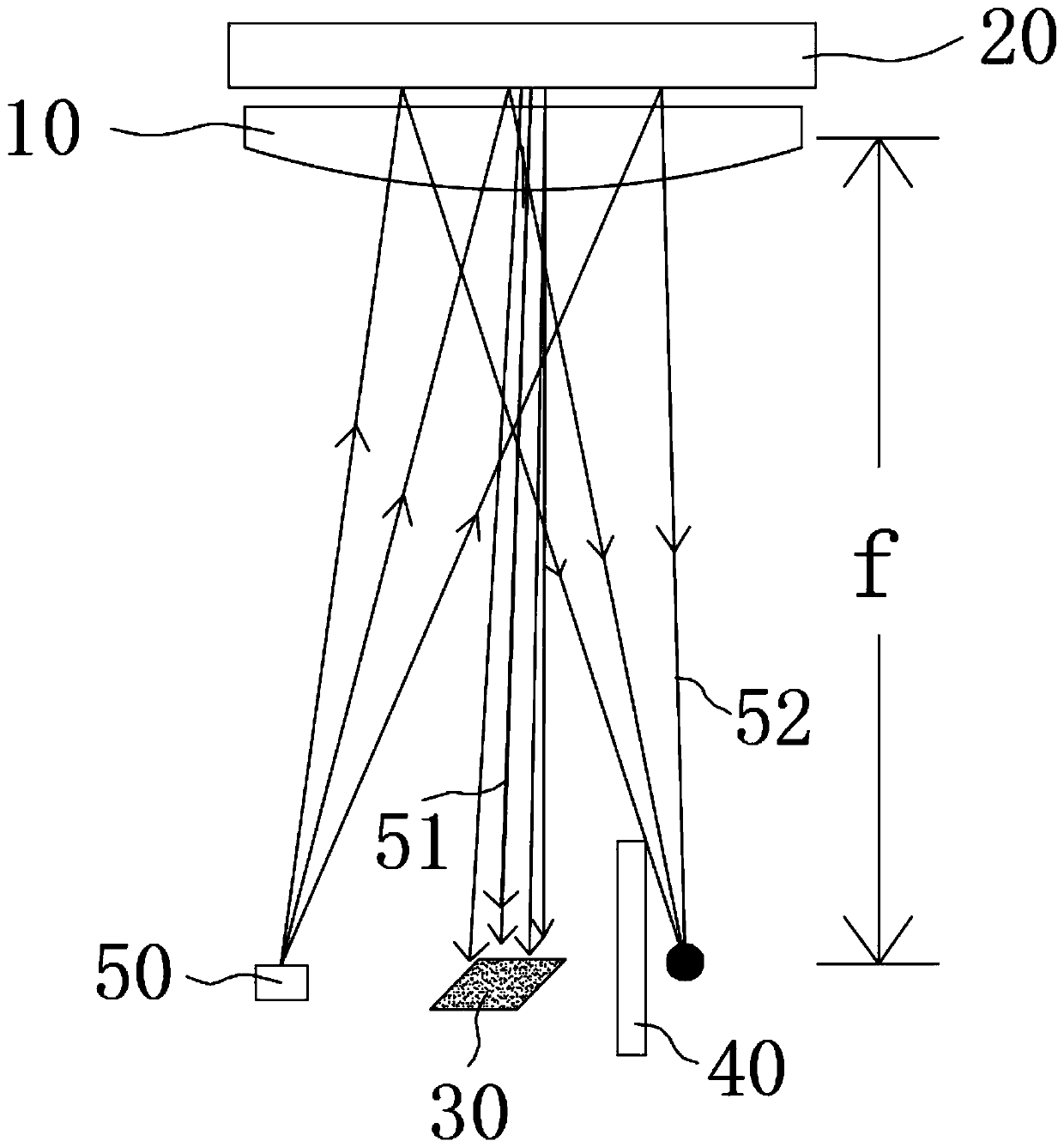
[0039] refer to Figure 1-Figure 4 As shown, the present invention discloses a spectroscopic measurement device based on a reflective random diffraction plate 20 , including a reflective random diffractive plate 20 , a collimating and focusing element 10 and a photodetector 30 .

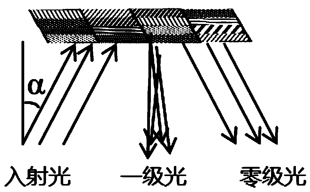
[0040] The reflective random diffraction sheet 20 includes a substrate, a metal reflective film and a diffraction grating unit. One side of the substrate is coated with a metal reflective film, and the other side of the substrate is engraved with a plurality of diffraction grating units. The density distribution is the same and the inclination direction of the notch is the same, but the density distribut...


PUM


Abstract

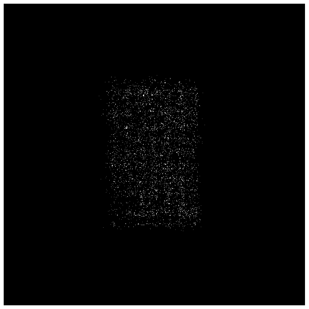
The invention discloses a spectral measurement device based on a reflective random diffraction sheet and a test method. The spectral measurement device comprises the reflective random diffraction sheet, a collimation focusing element and an optical detector, wherein the reflective random diffraction sheet comprises a substrate and a diffraction grating unit plated with a reflective film; the collimation focusing element is located at one side of the reflective random diffraction sheet, incident light passes through the collimation focusing element to become parallel light, the parallel light illuminates the reflective random diffraction sheet and is reflected by the reflective random diffraction sheet to obtain zero-level diffracted light and first-level diffracted light, the zero-level light is converged after passing through the collimation focusing element, and the first-level diffracted light forms a speckle pattern after passing through the collimation focusing element; and the optical detector is located at the side, away from the reflective random diffraction sheet, of the collimation focusing element and is used for receiving the speckle pattern. The device is high in spectral resolution, high in light energy utilization rate, compact in structure and small in size.

Description

technical field [0001] The invention relates to the technical field of spectrum detection, in particular to a spectrum measurement device and a test method based on a reflective random diffraction sheet. Background technique [0002] Cao Hui and others from Yale University built a set of ultra-high resolution miniature spectrometer system by using multimode optical fiber and camera. The spectral resolution is proportional to the length of the fiber. As long as the optical fiber is wound up, a high-resolution and compact micro-spectrometer can be realized. Wang Peng et al. at the University of Utah built a computational spectrometer using a self-made broadband diffraction element and detector array. The broadband diffraction element consists of a series of grooves with random depths. Using this structure, they obtained high-resolution and Miniature spectrometer with wide bandwidth. Based on the principle of multiple scattering and interference, Zhu YY of Nanjing University...

Claims


Application Information

Patent Timeline
Patent Type & Authority Applications(China)
IPC IPC(8): G01J3/28G01J3/18G01J3/02
CPCG01J3/28G01J3/18G01J3/0208G01J3/0256
Inventor 蔡志坚吴利胡祖元吴建宏
Owner SUZHOU UNIV
Learn More