
DC current limiting circuit breaker

A circuit breaker and circuit breaker technology, which is applied in the direction of circuit devices, emergency protection circuit devices, emergency protection devices with automatic disconnection, etc., can solve the problems of reduced reliability, high cost, and difficult implementation, so as to avoid re-shock, Improve the breaking speed and ensure the effect of arc extinguishing and breaking

Active Publication Date: 2021-11-02
INST OF ELECTRICAL ENG CHINESE ACAD OF SCI
View PDF7 Cites 0 Cited by
  • Summary
  • Abstract
  • Description
  • Claims
  • Application Information

AI Technical Summary

Problems solved by technology

However, there is a problem of long breaking and arc extinguishing time
If the method of pre-charging the parallel resonant circuit is used to increase the arc extinguishing speed of the circuit breaker, it is not only difficult to realize, but also the breaking speed is difficult to meet the needs of the DC power grid.
State Grid Smart Grid Research Institute took the simulation results of the five-terminal DC network in Zhoushan as an example, and concluded that the high-voltage DC circuit breaker needs to break the current of 15KA (design scheme of new high-voltage DC circuit breaker for flexible DC transmission network, Power System Automation, 2013, 37 (15):95-102.), the 320KV / 2KA hybrid high-voltage DC circuit breaker completed by ABB in 2012 (The HybridHVDC Breaker An innovation breakthrough enabling reliable HVDC grids. ABBGrid Systems, Technical Paper Nov'2012), can be broken The short-circuit current is 9kA, but it has not been put into commercial use due to the high cost, and the increase of the breaking capacity can only rely on the series-parallel connection of more IGBT units, which will greatly increase the cost of the circuit breaker and reduce the reliability

Method used


Image

  • DC current limiting circuit breaker
  • DC current limiting circuit breaker
  • DC current limiting circuit breaker

Examples


Embodiment Construction

[0067] Preferred embodiments of the present invention are described below with reference to the accompanying drawings. Those skilled in the art should understand that these embodiments are only used to explain the technical principle of the present invention, and are not intended to limit the protection scope of the present invention.

[0068] It should be noted that, in the description of the present invention, the terms "first" and "second" are only for the convenience of description, rather than indicating or implying the relative importance of the devices, elements or parameters, so they should not be understood as important to the present invention. Invention Limitations.

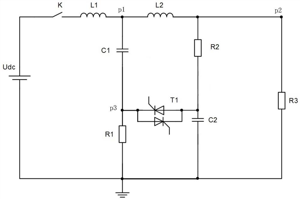
[0069] figure 1 It is a schematic diagram of the main components of Embodiment 1 of the DC current limiting circuit breaking device of the present invention. like figure 1 As shown, the breaking device includes: circuit breaker K, first reactor L1, second reactor L2, first capacitor C1, second capac...


PUM


Abstract

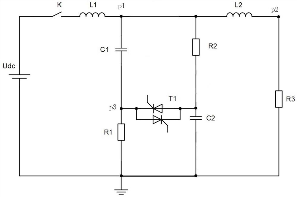
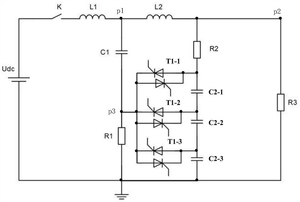
The invention relates to the field of circuit breakers, in particular to a DC current-limiting circuit breaker, which aims to limit short-circuit current and quickly break fault circuits. The DC current limiting circuit breaking device of the present invention comprises: a circuit breaker, a first reactor, a second reactor, a first capacitor, a second capacitor, a first resistor, a second resistor, a first controllable switch and a control unit. When the load starts, the control unit turns off the first controllable switch and closes the circuit breaker, and the DC power supply completes the charging of the first capacitor and the second capacitor through the charging circuit; when the load is short-circuited, the control unit turns off the first controllable switch The control switch is closed, so that the first capacitor and the second capacitor are connected in series, so that the voltage at the connection point p1 between the first capacitor and the first reactor increases, thereby limiting the magnitude of the DC power supply current and causing the circuit breaker to be extinguished and disconnected. The circuit breaking device of the present invention has simple structure and low cost, can effectively limit the short-circuit current of the multi-terminal flexible DC power grid, and realize fault circuit breaking.

Description

technical field [0001] The invention relates to the field of circuit breakers, in particular to a DC current limiting circuit breaker. Background technique [0002] With the development and application of new energy sources such as wind power and solar energy, the multi-terminal flexible DC transmission technology based on voltage source converters occupies an increasingly important position in the field of DC transmission. The biggest obstacle for new energy sources such as wind energy and solar power to connect to the grid is their intermittency and uncertainty, while the flexible DC transmission technology can effectively control power, isolate the spread of grid faults, and can quickly, flexibly, and A part of the energy is regulated to be emitted or absorbed, thereby optimizing the power flow distribution of the power grid, enhancing the stability of the power grid, and improving the intelligence and controllability of the power grid. [0003] Once a short-circuit faul...

Claims


Application Information

Patent Timeline
Patent Type & Authority Patents(China)
IPC IPC(8): H02H3/087H02H9/02
CPCH02H3/087H02H9/02
Inventor 肖立业张志丰滕尚甫余修勇韦统振邱清泉
Owner INST OF ELECTRICAL ENG CHINESE ACAD OF SCI
Learn More