
Laser welding joint crack detecting and intensifying system

A crack detection and laser welding technology, applied in laser welding equipment, welding equipment, metal processing equipment, etc., can solve problems such as reducing production efficiency, not well guaranteeing the quality of welded joints, and repeatedly clamping workpieces.

Pending Publication Date: 2019-07-26
GUANGDONG UNIV OF TECH
View PDF7 Cites 5 Cited by
  • Summary
  • Abstract
  • Description
  • Claims
  • Application Information

AI Technical Summary

Problems solved by technology

However, there is no system and device for real-time detection of crack defects in the laser welding process, which cannot guarantee the quality of welded joints; and the secondary strengthening treatment after laser welding requires repeated clamping of the workpiece, which consumes a lot of labor and damages the ring. The continuity of welding is seriously reduced, and the production efficiency is seriously reduced

Method used


Image

  • Laser welding joint crack detecting and intensifying system
  • Laser welding joint crack detecting and intensifying system

Examples


Embodiment Construction

[0022] The following will clearly and completely describe the technical solutions in the embodiments of the present invention with reference to the accompanying drawings in the embodiments of the present invention. Obviously, the described embodiments are only some, not all, embodiments of the present invention. Based on the embodiments of the present invention, all other embodiments obtained by persons of ordinary skill in the art without making creative efforts belong to the protection scope of the present invention.

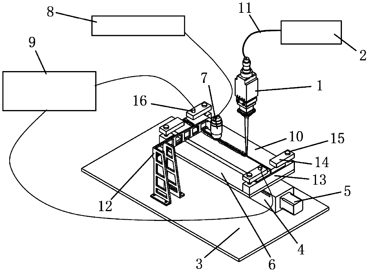
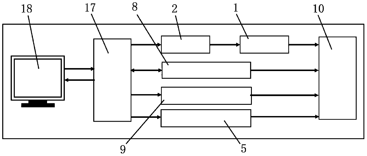
[0023] Please refer to figure 1 and figure 2 , figure 1 It is a schematic diagram of the overall structure of a specific embodiment provided by the present invention; figure 2 It is a structural block diagram of a specific embodiment provided by the present invention.

[0024] In a specific embodiment provided by the present invention, the laser welding joint crack detection and strengthening system mainly includes 1. A laser welding joint crack detection...


PUM


Abstract

The invention discloses a laser welding joint crack detecting and intensifying system which comprises a laser head, a laser, a bottom plate, a sliding rail, a driving device, a clamp bottom plate, anelectro magnetic acoustic transducer, an ultrasonic fault detector and a high-voltage discharger, wherein the laser head is connected with the laser; the sliding rail is mounted on the bottom plate; the driving device is connected with the sliding rail; the clamp bottom plate is mounted on the sliding rail and is used for mounting a to-be-welded workpiece; the laser head is mounted above the workpiece; the electro magnetic acoustic transducer is mounted above the welding seam of the workpiece; the ultrasonic fault detector is connected with the electro magnetic acoustic transducer; and the high-voltage discharger is connected with plate bodies on the two sides of the welding seam of the workpiece separately. According to the laser welding joint crack detecting and intensifying system, theelectro magnetic acoustic transducer collects the wavelength signal of the welding joint, the ultrasonic fault detector detects the quality problem of the welding joint, the high-voltage discharger repairs and eliminates the crack defect to intensify the performance of the welding joint; and welding, detection, and intensifying are carried out simultaneously to improve the detecting and finishingefficiency.

Description

technical field [0001] The invention relates to the technical field of laser welding, in particular to a crack detection and strengthening system for laser welding joints. Background technique [0002] Laser welding is a method of using a laser with high energy density as a heat source to heat and melt the workpiece to perform welding. It has the advantages of fast welding speed, small deformation, good joint quality, and small heat-affected zone. Laser welding can be applied to various metals Materials, and the advantages of being easy to automate are the hotspots of today's advanced manufacturing technology. [0003] The heat input and thermal influence of laser welding are much smaller than the traditional resistance welding process and arc welding process, but as a fusion welding process, its biggest problem is that thermal deformation still exists due to heat input, which still seriously affects the assembly accuracy of components in many cases and the overall performa...

Claims


Application Information

Patent Timeline
IPC IPC(8): B23K26/346B23K26/70
CPCB23K26/346B23K26/702
Inventor 丁心同游德勇丁树权吴华昶
Owner GUANGDONG UNIV OF TECH
Learn More