

Asphalt melting device for highway engineering
A melting device and engineering technology, applied in the direction of roads, roads, road repair, etc., can solve the problems of short residence time of asphalt blocks, poor crushing effect, uneven discharge, etc., to prolong melting time, good heat insulation effect, melting rate increase effect
- Summary
- Abstract
- Description
- Claims
- Application Information
AI Technical Summary
Problems solved by technology
Method used
Image

Examples
Embodiment 1
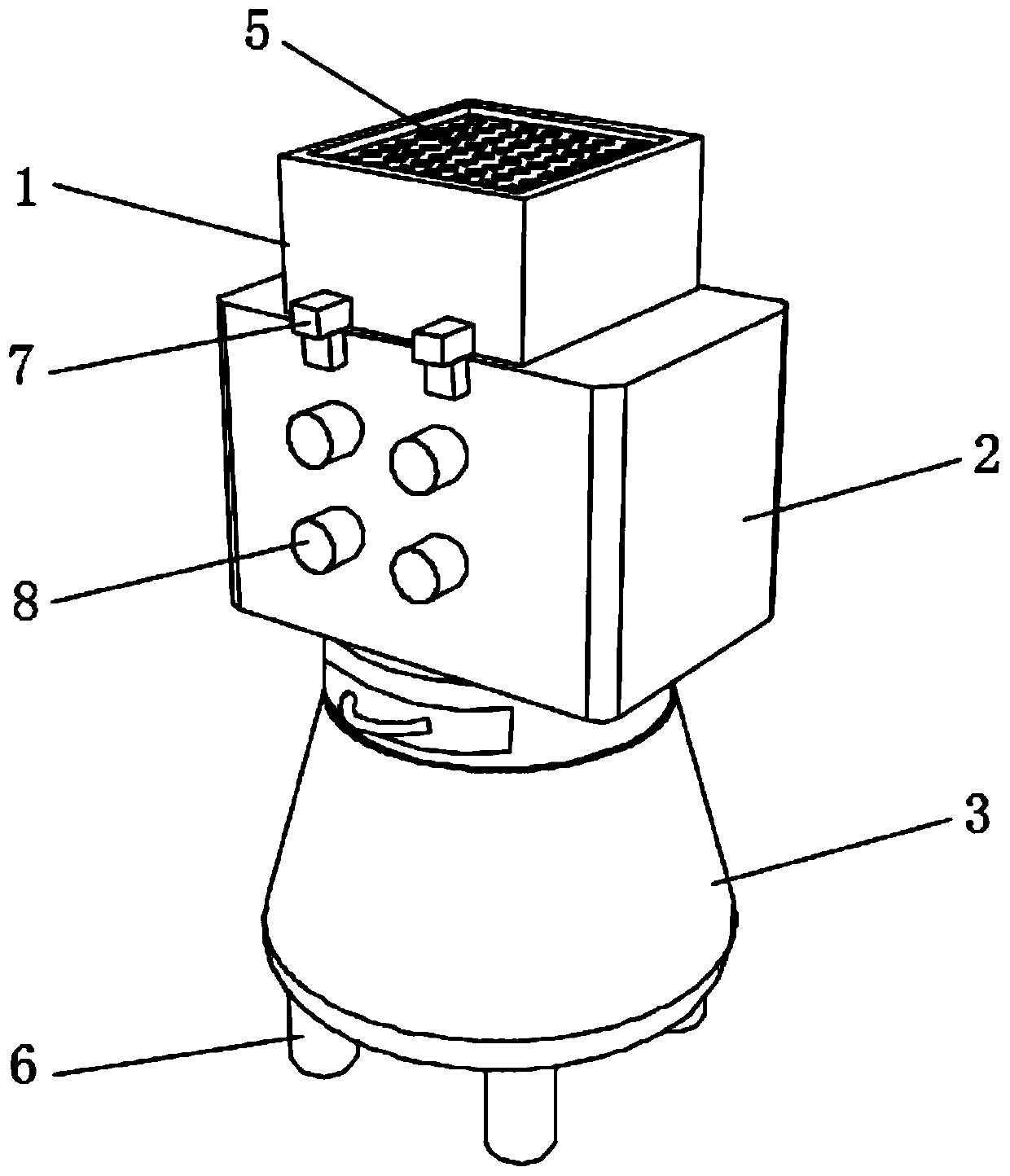
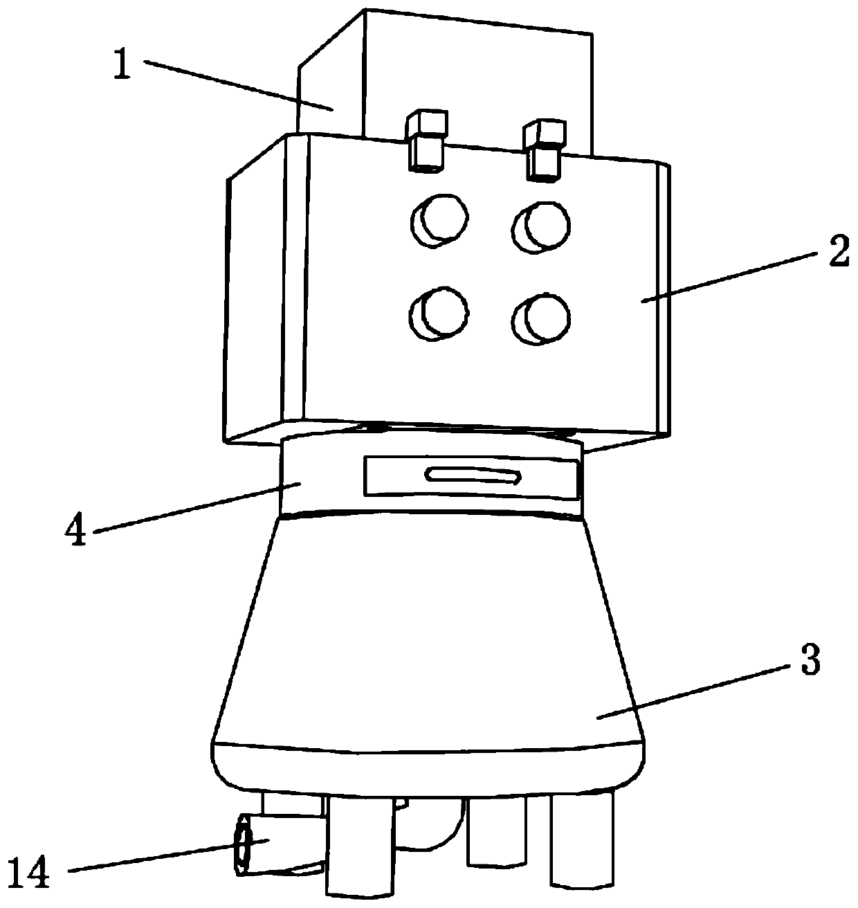
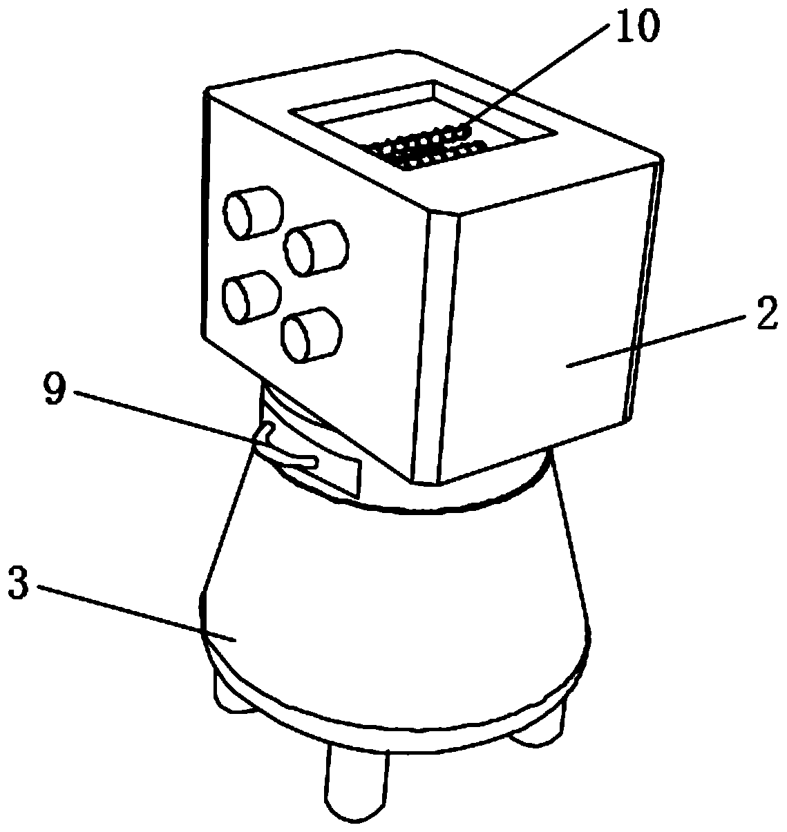
[0047] see figure 1 , an asphalt melting device for highway engineering, comprising a crushing mechanism 1, a melting mechanism 2, a filtering mechanism 4 and a thermal insulation mechanism 3, the crushing mechanism 1, the melting mechanism 2, the filtering mechanism 4 and the thermal insulation mechanism 3 are connected sequentially from top to bottom and mutually Connected, the lower end of the heat preservation mechanism 3 is fixedly connected with two pairs of support legs 6, and the whole device uses nano-microporous heat-insulating materials, nano-silicon dioxide and infrared blocking materials, and its heat-insulating effect is better than that of traditional heat-insulating materials such as ceramic fibers. material three to four times, see figure 2 , the center of the bottom end of the heat preservation mechanism 3 is fixedly connected with a discharge pipe 14, the side end of the filter mechanism 4 is connected with a filter drawer 9, the upper end of the crushing m...
Embodiment 2
[0060] see Figure 8-11, on the basis of Embodiment 1, adjust the steering of the auxiliary motor unit, the rotation direction of the auxiliary motor 8 located at the upper left side and the lower right side of the melting mechanism 2 is counterclockwise, and the rotation direction of the auxiliary motor 8 located at the lower left side and upper right side of the melting mechanism 2 The direction of rotation is clockwise, and a sealing port is provided at the center of the auxiliary motor unit, and a sealing cover 17 is connected to the sealing port, and a through hole is also opened on the sealing cover 17 and the main motor 16 is installed, and the power output end of the main motor 16 A winding roller 18 is fixedly connected through the through hole, and a fixed roller 19 is connected to the side of the sealing cover plate 17 located inside the melting mechanism 2. The fixed roller 19 is provided with an opening 20, and the surface of the winding roller 18 is evenly distrib...
PUM
 Abstract
Description
Claims
Application Information