Hot air valve for wax removal, hot air wax removal system and artificial intelligence wax removal method

A technology of hot air and valves, applied in sliding valves, valve devices, earthwork drilling and mining, etc., can solve the problems of high cost of wax removal, high power consumption, and only reverse cycle hot washing, etc., and achieve the effect of low cost of wax removal

Inactive Publication Date: 2019-07-26
张东林 +2
View PDF7 Cites 1 Cited by
  • Summary
  • Abstract
  • Description
  • Claims
  • Application Information

AI Technical Summary

Problems solved by technology

Existing wax removal methods include chemical method, thermal energy cleaning method, and mechanical wax scraping method. The chemical method uses chemical preparations to suppress wax formation, but the chemical preparations are easy to lose quickly with the liquid, and need to be refilled repeatedly to remove wax. High cost
The thermal energy cleaning method is to use a movable boiler to heat the oil well under high pressure. During cleaning, only reverse circulation heat cleaning is possible. The heat energy is injected from the casing and comes out from the oil pipe. Due to the temperature resistance limit of the underground submersible oil pump, the injection temperature can only be below 60°C , because the melting point of wax is 53°C, so the efficiency is not high, and this method is generally not used
The mechanical wax scraping method takes too long, and generally requires oil wells to be shut down for 4 to 8 hours, which affects oil production
Others proposed to directly energize the well pipe to heat and remove wax, but the power consumption is too large, and there are also potential safety hazards

Method used


Image

  • Hot air valve for wax removal, hot air wax removal system and artificial intelligence wax removal method
  • Hot air valve for wax removal, hot air wax removal system and artificial intelligence wax removal method
  • Hot air valve for wax removal, hot air wax removal system and artificial intelligence wax removal method

Examples


Embodiment Construction

[0026] The present invention will be described in further detail below in conjunction with the accompanying drawings: the present embodiment is implemented on the premise of the technical solution of the present invention, and detailed implementation is provided, but the protection scope of the present invention is not limited to the following embodiments.

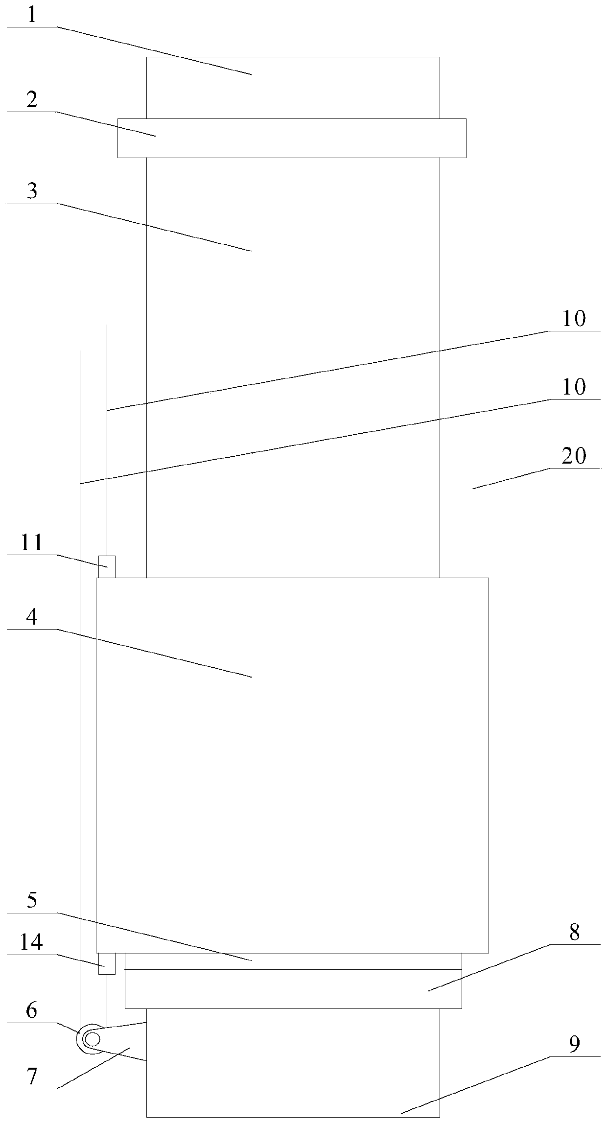
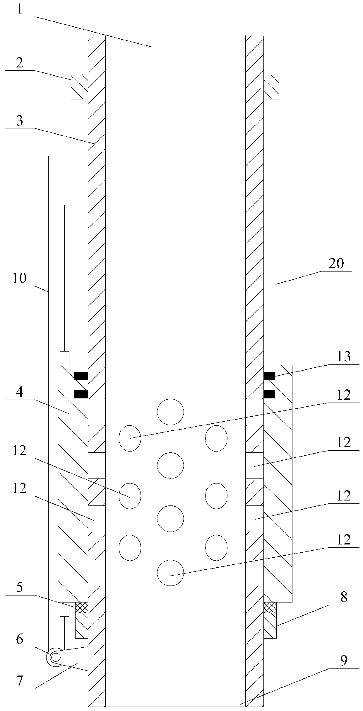
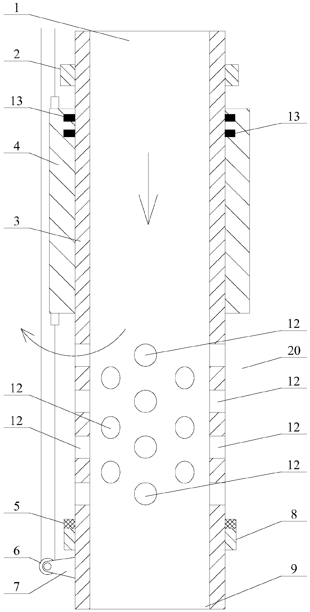
[0027] like Figure 1 ~ Figure 3 As shown, a hot air valve for wax removal involved in this embodiment, the hot air valve 20 includes an upper ferrule 2, an inner pipe 3, an outer pipe 4, a sealing gasket 5, a pulley 6, a pulley frame 7, and a lower ferrule 8. Steel wire rope 10, upper steel wire rope fastener 11, piston ring 13 and lower steel wire rope fastener 14, the outer pipe 4 is set on the inner pipe 3, the outer pipe 4 and the inner pipe 3 are slidingly connected, and the inner pipe 3 The lower part is provided with some hot air passage holes 12 within a range less than the height of the outer pipe 4, the upper en...


PUM


Abstract

The invention discloses a hot air valve for wax removal, a hot air wax removal system and an artificial intelligence wax removal method. The hot air valve comprises an upper hoop, an inner pipe, an outer pipe, a sealing gasket, a pulley, a pulley yoke, a lower hoop, a steel wire rope, an upper steel wire rope fastener, piston rings and a lower steel wire rope fastener; the wax removal system comprises the hot air valve, a hot air pipeline, a hot air pipeline valve, an oil discharging pipeline valve, an oil discharging pipeline, a servo motor, an induced draft fan, an annulus, a tee joint, an oil well casing and an oil well pipe; and the method comprises the steps: work of an oil-submerged pump is stopped; the oil discharging pipeline valve is closed; the servo motor is started to lift theouter pipe to enable hot air through holes to be exposed; the induced draft fan is started, and thus the oil well pipe, the hot air valve and the annulus are in a negative pressure state; hot air generated by an air heater is driven into the oil well pipe, and thus the hot air flows in the oil well pipe, the hot air valve and the annulus; after wax removal is completed, an air blower, the induceddraft fan and the hot air pipeline valve are sequentially stopped / closed; the servo motor is started to enable the outer pipe to lower to close the hot air through holes; and the oil discharging pipeline valve is opened, and wax removal work is completed.

Description

technical field [0001] The invention relates to a hot air valve for wax removal, a hot air wax removal system and an artificial intelligence wax removal method, belonging to the technical field of hot air wax removal. Background technique [0002] During the oil production process in the oil field, the oil-containing mixture is produced from the downhole. With the decrease of temperature and pressure and the precipitation of gas, the paraffin dissolved in the crude oil will crystallize and precipitate, and gradually accumulate on the inner wall surface of the oil pipe. Wax deposition on oil well pipe wall has been a difficult technical problem for many years. Existing wax removal methods include chemical method, thermal energy cleaning method, and mechanical wax scraping method. The chemical method uses chemical preparations to suppress wax formation, but the chemical preparations are easy to lose quickly with the liquid, and need to be refilled repeatedly to remove wax. Hi...

Claims


Application Information

Patent Timeline
Patent Type & Authority Applications(China)
IPC IPC(8): E21B37/00E21B36/00F16K3/26
CPCE21B36/00E21B37/00F16K3/262
Inventor 张东波张熠天赵志有
Owner 张东林
Why Eureka
Try Eureka