Same-side differential feeding substrate integrated waveguide slot antenna
A technology of substrate integrated waveguide and slot antenna, applied in the direction of slot antenna, antenna grounding switch structure connection, circuit, etc., can solve the problems of loss differential signal phase and amplitude imbalance, long distance, unfavorable differential circuit integration, etc., to achieve good Effects of common mode suppression, distance shortening, and loss avoidance
- Summary
- Abstract
- Description
- Claims
- Application Information
AI Technical Summary
Problems solved by technology
Method used
Image
Examples
Embodiment 1
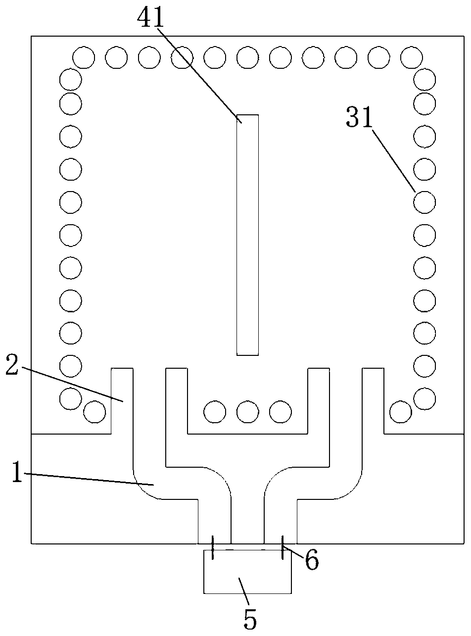
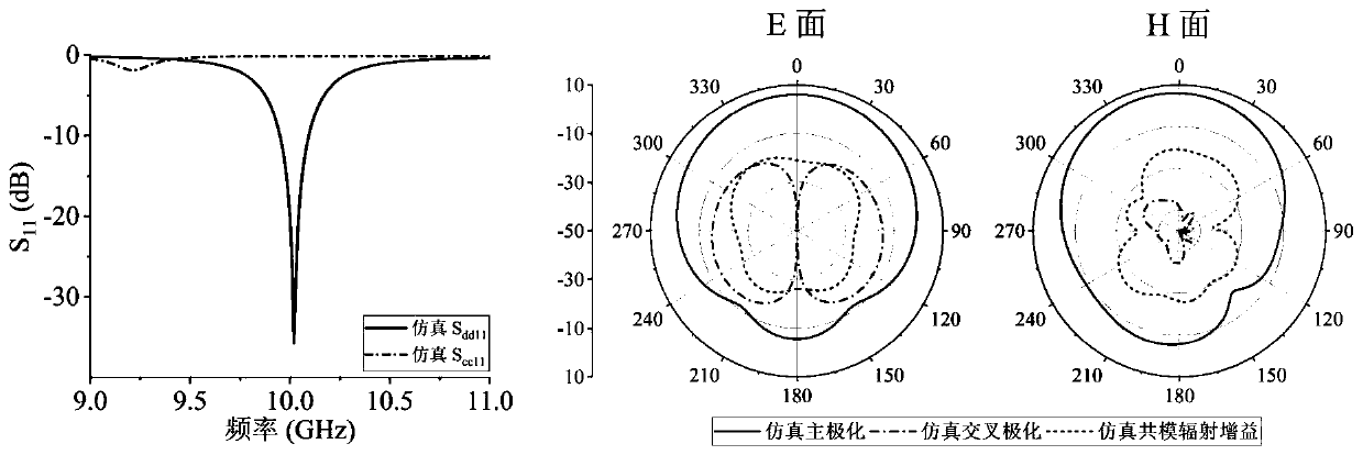
[0031] In this embodiment, the same-side differentially fed substrate-integrated waveguide slot antenna is in resonance at TE 120 mode, such as figure 1 , figure 2 and Figure 13 As shown, the antenna includes a first substrate-integrated waveguide cavity 31 composed of a metallized through-hole array and a differential feeding transmission line 1. The specific arrangement of the metallized through-hole array is as follows figure 1 As shown, the two transmission lines of the differential feeding transmission line 1 are located on the same side of the first substrate integrated waveguide cavity 31 and arranged symmetrically, and the two transmission lines of the differential feeding transmission line 1 pass through two coupling structures 2 (transition structures) and The first substrate integrated waveguide cavity 31 is coupled, the two transmission lines of the differential feed transmission line 1 are directly connected to the differential circuit 5 through the gold wire ...
Embodiment 2
[0035] In this embodiment, the same-side differentially fed substrate-integrated waveguide slot antenna is in resonance at TE 220 mode, such as Figure 4 and Figure 5 As shown, the antenna includes a second substrate integrated waveguide cavity 32 composed of a metallized through hole array and a differential feeding transmission line 1. The specific arrangement of the metallized through hole array is as follows Figure 4 As shown, the two transmission lines of the differential feeding transmission line 1 are located on the same side of the second substrate integrated waveguide cavity 32 and arranged symmetrically, and the two transmission lines of the differential feeding transmission line 1 pass through two coupling structures 2 (transition structures) and The second substrate integrated waveguide cavity 32 is coupled, the two transmission lines of the differential feed transmission line 1 are directly connected to the differential circuit 5 through the gold wire bonding w...
Embodiment 3
[0039] In this embodiment, the same-side differentially fed substrate-integrated waveguide slot antenna adopts the method of direct bonding between the differentially grounded coplanar waveguide and the chip, as shown in Figure 7 and Figure 8 As shown, the antenna includes a third substrate integrated waveguide cavity 33 composed of a metallized through-hole array and a differential feed transmission line 1 (this embodiment is a differentially grounded coplanar waveguide transmission line). The specific arrangement of the metallized through-hole array is as follows Figure 7 As shown, the two transmission lines of the differential feeding transmission line 1 are located on the same side of the third substrate integrated waveguide cavity 33 and arranged symmetrically, and the two transmission lines of the differential feeding transmission line 1 pass through two coupling structures 2 (transition structures) and The third substrate integrated waveguide cavity 33 is coupled, th...
PUM
 Abstract
Description
Claims
Application Information
 - R&D
- Intellectual Property
- Life Sciences
- Materials
- Tech Scout
- Unparalleled Data Quality
- Higher Quality Content
- 60% Fewer Hallucinations
Browse by: Latest US Patents, China's latest patents, Technical Efficacy Thesaurus, Application Domain, Technology Topic, Popular Technical Reports.
© 2025 PatSnap. All rights reserved.Legal|Privacy policy|Modern Slavery Act Transparency Statement|Sitemap|About US| Contact US: help@patsnap.com


