Power conversion device and air conditioning device using same

A technology for a power conversion device and an air-conditioning device, which is applied in the fields of power conversion devices and air-conditioning devices, can solve the problems of large surge voltage, the same plane, and the circuit where the connector cannot flow with a large current, etc., to achieve impedance reduction and shock reduction. The effect of voltage

Active Publication Date: 2019-07-26
MITSUBISHI ELECTRIC CORP
View PDF7 Cites 0 Cited by
  • Summary
  • Abstract
  • Description
  • Claims
  • Application Information

AI Technical Summary

Problems solved by technology

The surge voltage due to L(di / dt) increases due to the length of the wiring
In addition, there are cases where it is not possible to arrange the two substrates on the same plane due to the space constraints of the device where the converter device is installed.
[0007] In the printed wiring board connection structure disclosed in Patent Document 2, connectors are used to connect paths of electrical signals flowing between boards, but such connectors cannot be used for power supplies such as inverter circuits and boost converter circuits. Circuits where large currents flow

Method used


Image

  • Power conversion device and air conditioning device using same
  • Power conversion device and air conditioning device using same
  • Power conversion device and air conditioning device using same

Examples


Embodiment approach 1

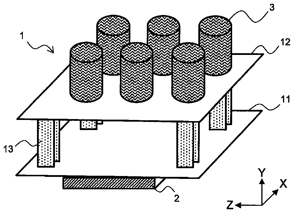
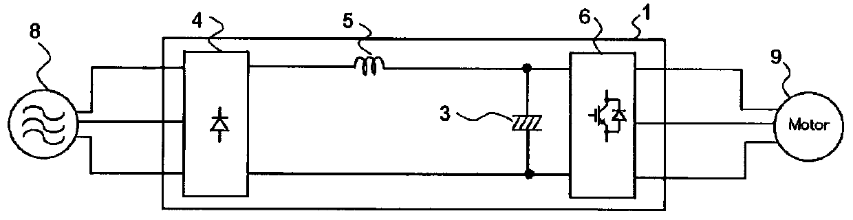
[0024] The configuration of the power conversion device according to Embodiment 1 will be described with reference to the drawings. figure 1 It is an external perspective view showing a configuration example of the power conversion device according to Embodiment 1 of the present invention. figure 2 yes means figure 1 A circuit diagram of a configuration example of the power conversion device shown.

[0025] Such as figure 1 As shown, the power conversion device 1 has: a first substrate 11 on which the module 2 is mounted; a second substrate 12 on which the smoothing capacitor 3 is mounted; and a terminal block 13 that connects the first substrate 11 and the second substrate 12 . The first substrate 11 and the second substrate 12 are arranged to face each other so that their respective substrate surfaces are parallel. The terminal block 13 plays a role of physically and electrically connecting the two substrates. exist figure 1 In the first substrate 11 and the second sub...

Deformed example 1

[0048] Next, Modification 1 of the power conversion device 1 according to Embodiment 1 will be described. Figure 5 It is a plan view of the second substrate of Modification 1 of the power conversion device 1 according to Embodiment 1 of the present invention.

[0049] exist figure 1 In the illustrated power conversion device 1 , the second substrate 12 is arranged in a direction perpendicular to the substrate surface of the first substrate 11 . Therefore, when the second board 12 is mounted on the terminal block 13 , it is difficult for the operator to access the board surface of the first board 11 when screwing the first board 11 to the control box 45 or removing the screws. In modification 1, such as Figure 5 As shown, the second substrate 12 is provided with a hole 21 penetrating through the second substrate 12 . exist Figure 5 In the shown configuration example, a total of four holes 21 are provided between the smoothing capacitors 3 . When fixing the first substra...

Deformed example 2

[0055] Next, Modification 2 of the power conversion device 1 according to Embodiment 1 will be described. Figure 6A It is a diagram showing the configuration of Modification 2 of the power conversion device according to Embodiment 1 of the present invention. Figure 6B yes Figure 6A A top view of the first substrate is shown. In addition, in Figure 6A , omitted in the figure to show figure 1 In the shown power conversion device 1 , the structure other than the first substrate 11 and the terminal block 13 is shown. In addition, the case where the power conversion device 1 is attached to the side surface of the control box 45 will be described.

[0056] In the power conversion device 1 according to Modification 2, a first terminal block 13 a and a second terminal block 13 b are provided as the terminal block 13 . Such as Figure 6A as well as Figure 6B As shown, the first terminal block 13a and Figure 4B The illustrated terminal block 13 is the same, and is arranged...


PUM


Abstract

Provided is a power conversion device that includes the following: a first substrate on which a module that includes a switching element is mounted; a second substrate on which a smoothing capacitor is mounted; and a terminal block that connects the first substrate and the second substrate which are disposed so as to face each other, and that is provided with a current pathway through which flowsat least the current that flows from the module to the smoothing capacitor or the current that flows from the smoothing capacitor to the module.

Description

technical field [0001] The present invention relates to a power conversion device having a switching element and an air conditioner using the power conversion device. Background technique [0002] The refrigerating and air-conditioning apparatus has a large-capacity inverter device that drives a motor such as a compressor and a fan. The converter of the three-phase full-wave rectification method provided in the converter device includes a three-phase rectifier for rectifying the three-phase AC voltage, a reactor for smoothing the output voltage of the three-phase rectifier, a smoothing capacitor, and a smoothing capacitor. An inverter circuit that converts voltage into AC voltage to drive a motor. In this three-phase full-wave rectification type converter, there is a step-up converter for boosting the output voltage of the three-phase rectifier by chopping for the purpose of improving the power factor of the power supply and harmonics of the power supply current, and a boos...

Claims


Application Information

Patent Timeline
Patent Type & Authority Applications(China)
IPC IPC(8): H02M7/48
CPCH02M7/48H02M7/003H02M7/5387H01R12/55H01R12/52H01R4/30H05K7/14322F25B31/02H02P27/06H02P2201/03
Inventor 汤浅健太谷口喜浩野月善一
Owner MITSUBISHI ELECTRIC CORP
Why Eureka
Try Eureka