
Accelerator cap structure based on reducing rejection rate

A technology of accelerator and cap structure, which is applied to casting molding equipment, casting molds, cores, etc., can solve the problem of small feeding capacity of bottom casting risers, uneven casting riser allowance, and unqualified parts air tightness, etc. problems, to achieve the effect of improving machining speed and quality, improving product quality and yield, and avoiding shrinkage cavities

Inactive Publication Date: 2019-07-30
十堰锦天汽车零部件有限公司
View PDF0 Cites 0 Cited by
  • Summary
  • Abstract
  • Description
  • Claims
  • Application Information

AI Technical Summary

Problems solved by technology

[0005] In order to solve the above-mentioned technical problems, the present invention provides a booster cap structure based on reducing the scrap rate, so as to solve the problem that in the existing booster cap casting, the casting riser is located at the bottom surface, close to the mating surface, and it is easy to get stuck on the mating surface during the casting process. Shrinkage cavities are generated at the parts, resulting in unqualified air tightness of parts and leakage accidents in assembly. At the same time, the small feeding capacity of the casting riser on the bottom surface is limited. At the same time, the allowance at the casting riser is uneven, which needs to be avoided during machining. A large amount of empty tool time affects the machining efficiency

Method used


Image

  • Accelerator cap structure based on reducing rejection rate
  • Accelerator cap structure based on reducing rejection rate
  • Accelerator cap structure based on reducing rejection rate

Examples


Embodiment

[0027] as attached figure 1 to attach Figure 5 Shown:

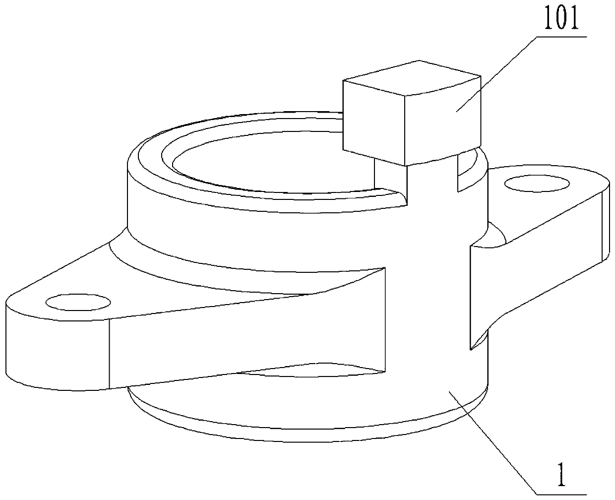
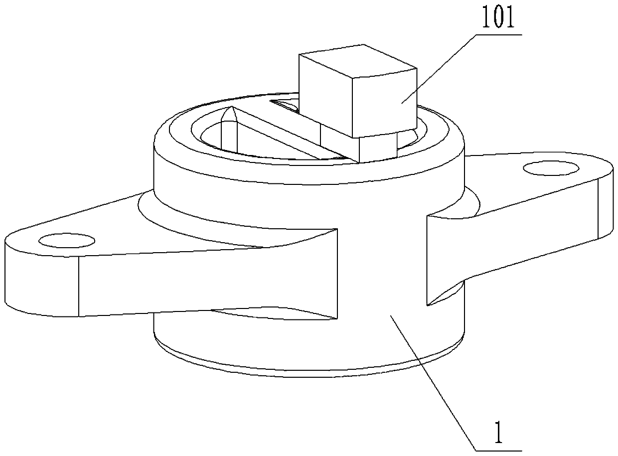
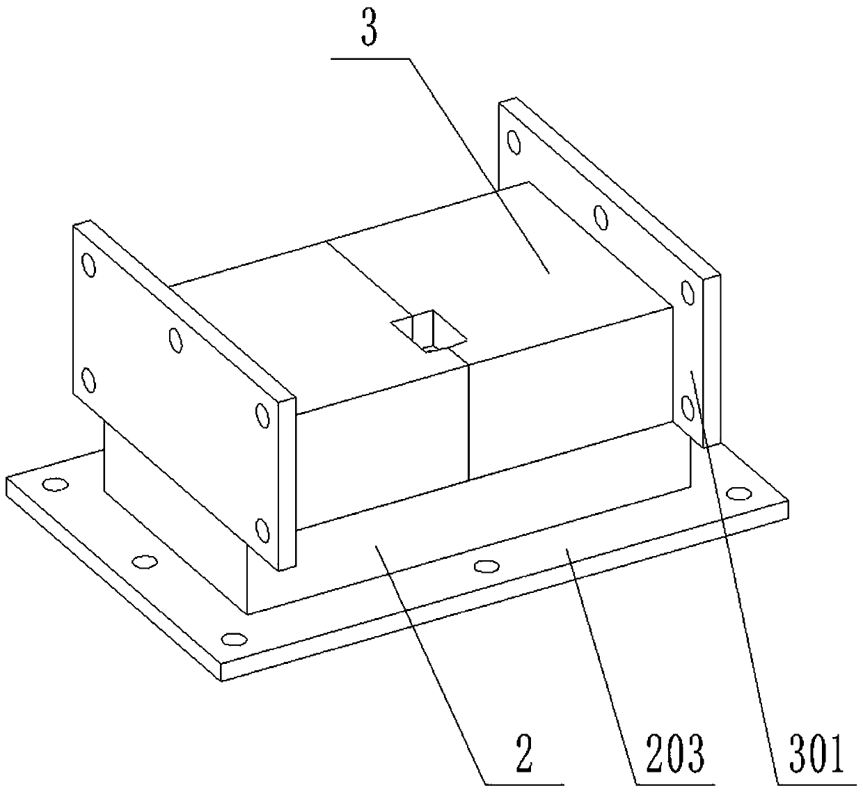
[0028] The present invention provides a accelerator cap structure based on reducing the scrap rate, including accelerator cap 1, casting riser 101, bottom mold 2, cooling copper rod 201, cooling iron 202, bottom flange 203, side mold 3 and side method Lan 301; the casting mold of the accelerator cap 1 is composed of two sets of side molds 3 and a set of bottom molds 2; the side molds 3 are located on the left and right sides above the bottom mold 2.

[0029] Wherein, the top of the booster cap 1 is provided with a set of casting risers 101, the casting risers 101 are located at the handle of the booster cap 1 and avoid rounded corners, changing the traditional 1. Setting it on the mating surface will easily cause shrinkage cavity on the mating surface and cause leakage accidents in assembly. At the same time, the casting riser 101 is set at the handle of the accelerator cap 1. The volume of the casting riser 101 can be...


PUM


Abstract

The invention provides an accelerator cap structure based on reducing the rejection rate. The promoter cap structure comprises an accelerator cap, a casting head, a bottom mold, cooling copper rods, cooling iron, a bottom flange, side molds and side flanges; a casting mold of the accelerator cap is composed of two groups of side molds and a group of bottom mold; the side molds are positioned on the left sides and the right sides above the bottom mold. According to the accelerator cap structure, the feeding capacity can be effectively improved, the occurrence of shrinkage porosity and shrinkagecan be reduced, the casting quality can be improved, hole shrinkage of the matching surface can be effectively avoided, and the product quality and the yield are improved; and meanwhile, the positionof the casting head is easy to polish and clean, the processing allowance of the matching surface is uniform, and the processing speed and quality of the subsequent machining are improved.

Description

technical field [0001] The invention belongs to the technical field of casting, and more specifically relates to a accelerator cap structure based on reducing the scrap rate. Background technique [0002] In the production of the accelerator cap, casting is generally used for production, and in the casting of the accelerator cap, the casting riser is generally arranged on the lower surface of the accelerator cap. [0003] Based on the above, in the existing booster cap casting, the casting riser is located at the bottom surface, close to the mating surface, and shrinkage cavities are likely to occur at the mating surface during the casting process, resulting in unqualified air tightness of the parts and leakage accidents in assembly. The small feeding capacity of the bottom casting riser is limited, and the margin at the casting riser is uneven, so it is necessary to avoid a large amount of empty tool time during machining, which affects the machining efficiency. [0004] T...

Claims


Application Information

Patent Timeline
Patent Type & Authority Applications(China)
IPC IPC(8): B22C9/08
CPCB22C9/088
Inventor 陈广良段传刚郑涛许志武黄森亮刘成林梁吉峰陈蒙清
Owner 十堰锦天汽车零部件有限公司
Learn More