
Method for realizing high-speed cutting by using cutting head swing in laser tube cutter

A laser cutting head and pipe cutting machine technology, applied in laser welding equipment, applications, household appliances, etc., can solve the problems of cutting speed and acceleration limitation, low dynamic performance, limited maximum cutting speed and acceleration, etc. Achieve the effect of accelerating cutting speed, simple method and improving processing efficiency

Active Publication Date: 2019-07-30
FOSHAN HONGSHI LASER TECH CO LTD
View PDF5 Cites 4 Cited by
  • Summary
  • Abstract
  • Description
  • Claims
  • Application Information

AI Technical Summary

Problems solved by technology

In this conventional cutting method, the maximum cutting speed and acceleration are limited by the mechanical and electrical properties of the X-axis and Y-axis, because the X-axis of the laser tube cutting machine needs to drive a large chuck load, and the dynamic performance is not significantly high. Therefore, the cutting speed and acceleration in the X direction are greatly restricted

Method used


Image

  • Method for realizing high-speed cutting by using cutting head swing in laser tube cutter
  • Method for realizing high-speed cutting by using cutting head swing in laser tube cutter
  • Method for realizing high-speed cutting by using cutting head swing in laser tube cutter

Examples


Embodiment Construction

[0021] The specific embodiments of the present invention will be further described below in conjunction with the drawings:

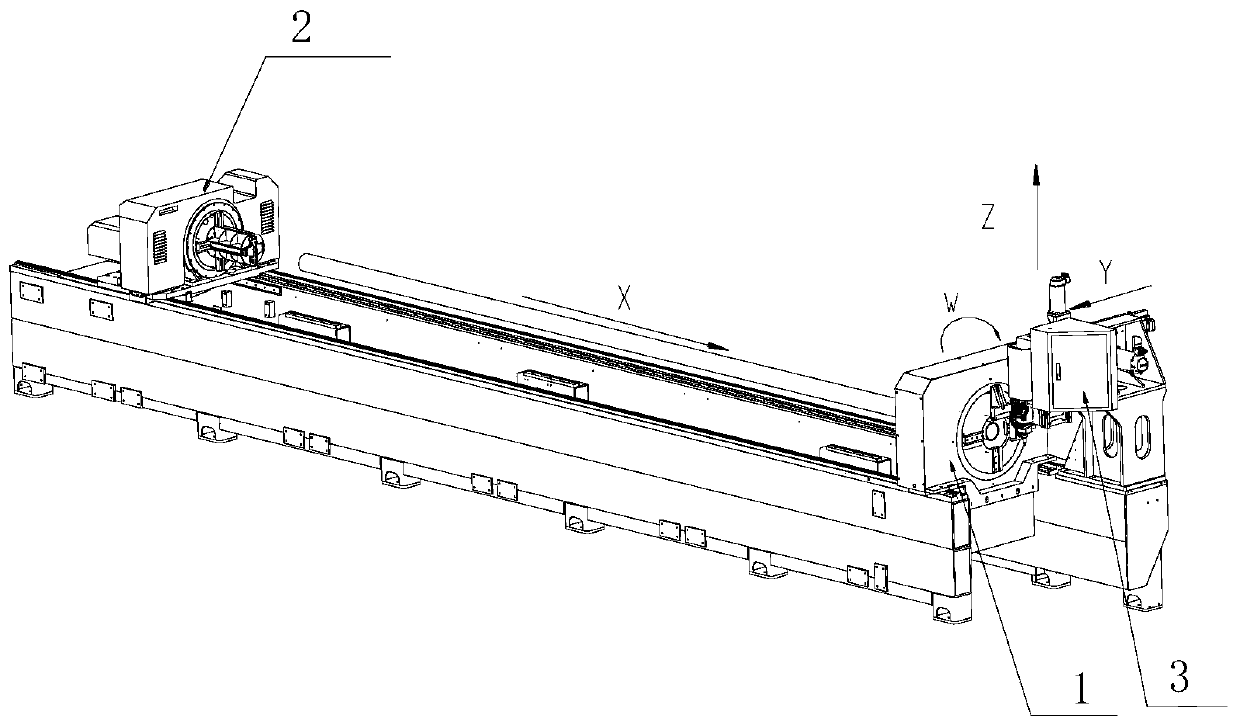
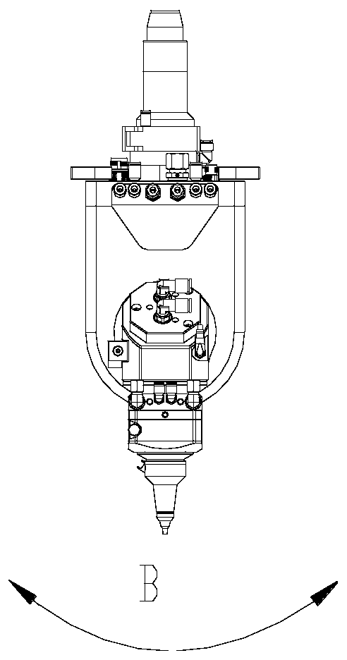
[0022] The laser pipe cutting machine includes a front chuck and a rear chuck. The rear chuck can drive the cut pipe to move in the X direction. The front chuck includes a front end and a rear end. The front end of the front chuck is far away One end of the rear chuck, the rear end of the front chuck is an end close to the rear chuck, a laser cutting head is provided at the front end of the front chuck, and the laser cutting head can be along the Y direction And moving in the Z direction, the laser pipe cutting machine includes an image processing module and a cutting execution module, the image processing module is electrically connected to the cutting execution module, and the laser cutting head can swing around the Y axis, such as figure 2 As shown, the swing direction is the B axis direction, θ max Is the maximum allowable swing amplitude of the laser ...


PUM


Abstract

The invention discloses a method for realizing high-speed cutting by using cutting head swing in a laser tube cutter. In the laser tube cutter, a cutting head which can swing by taking a Y-axis as a center axis is utilized to assist interpolation motion, so that high-speed cutting is realized; component, in the X direction, of the swinging laser cutting head is superposed into a cutting outline, so that cutting speed, in the X direction, of the cutting outline is quickened and integral processing efficiency is improved; and moreover, the method provided by the invention is simple, and is liable to realize.

Description

Technical field [0001] The invention relates to the field of laser cutting, and in particular to a method for realizing high-speed cutting by swinging a cutting head in a laser pipe cutting machine. Background technique [0002] Laser pipe cutting machine is a special equipment for cutting, welding, marking, engraving, surface treatment, fine processing and other technological processes of pipes using high-energy laser beams. The laser pipe cutting machine processing system is composed of at least six parts, namely the pipe cutting machine body, chuck, laser, laser cutting head, height tracking system, electrical control system, etc. In the current processing technology, equipment energy consumption and auxiliary material loss are relatively large. When this part of the loss cannot be reduced, how to achieve a higher processing speed and reduce the processing time of a single part and the entire pipe is particularly important. [0003] In the traditional laser pipe cutting machine...

Claims


Application Information

Patent Timeline
IPC IPC(8): B23K26/38B23K26/08B23K26/03B23K101/06
CPCB23K26/032B23K26/0876B23K26/38B23K2101/06
Inventor 夏宇锐刘洋常勇
Owner FOSHAN HONGSHI LASER TECH CO LTD
Features
  • Generate Ideas
  • Intellectual Property
  • Life Sciences
  • Materials
  • Tech Scout
  • Unparalleled Data Quality
  • Higher Quality Content
  • 60% Fewer Hallucinations
Learn More