Double-beam laser processing optical system

A laser processing and optical system technology, applied in metal processing equipment, laser welding equipment, manufacturing tools, etc., can solve the problems of high price, complicated optical path design, inconvenient installation and adjustment, etc., and achieve the effect of improving laser processing efficiency

Pending Publication Date: 2019-08-02
HUAZHONG UNIV OF SCI & TECH
View PDF0 Cites 5 Cited by
  • Summary
  • Abstract
  • Description
  • Claims
  • Application Information

AI Technical Summary

Problems solved by technology

[0004] In view of the above defects or improvement needs of the prior art, the object of the present invention is to provide a dual-beam laser processing optical system. By improving the composition of each component in the laser processing optical system and their interaction, the introduction of The focused spot on the laser processing path always maintains the relative position of the main laser focused spot and the auxiliary laser achieves dual beams, which can overcome the high

Method used


Image

  • Double-beam laser processing optical system
  • Double-beam laser processing optical system
  • Double-beam laser processing optical system

Examples


Example Embodiment

[0040] Example one:

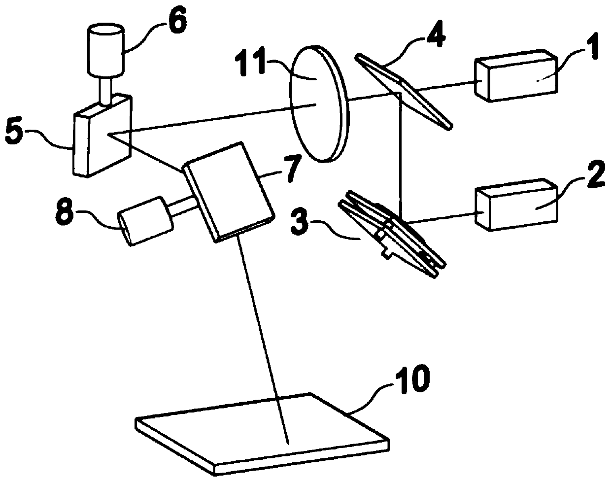
[0041] The schematic diagram of the first embodiment of the dual-beam laser processing optical system of the present invention is as follows figure 1 As shown, the dual-beam laser processing optical system consists of nanosecond pulsed fiber laser 1, continuous semiconductor laser 2, adjustable deflection direction mirror 3, wavelength beam combiner 4, telephoto mirror 11, scanning galvanometer group (including X galvanometer 6, X scanning mirror 5, Y galvanometer 8, Y scanning mirror 7) and the workpiece 10 constitute, the telephoto lens 11 is placed in the wavelength beam combiner 4 and includes X galvanometer 6, X scanning mirror 5 and Y vibration Between the mirror 8 and the scanning galvanometer group of the Y scanning mirror 7, the auxiliary laser light emitted by the continuous semiconductor laser 2 is reflected by the mirror 3 with adjustable deflection direction and then enters the wavelength beam combiner 4, and the main laser light emitted by the n...

Example Embodiment

[0045] Embodiment two:

[0046] The schematic diagram of the second embodiment of the dual-beam laser processing optical system of the present invention is as follows: Figure 5 As shown, the dual-beam laser processing optical system consists of a nanosecond pulsed fiber laser, a continuous semiconductor laser, a mirror with adjustable deflection direction, a wavelength beam combiner, a field lens, including X galvanometer, X scanning mirror, and Y galvanometer. The scanning galvanometer group of the scanning mirror and the workpiece are formed. The field lens is placed between the scanning galvanometer group including X galvanometer, X scanning mirror, Y galvanometer and Y scanning mirror, and the workpiece. The auxiliary laser emitted by the continuous semiconductor laser is deflected by adjustable The reflection mirror in the direction of the mirror enters the wavelength combiner, the main laser emitted by the nanosecond pulse fiber laser enters the wavelength combiner, the mai...

Example Embodiment

[0048] Example three:

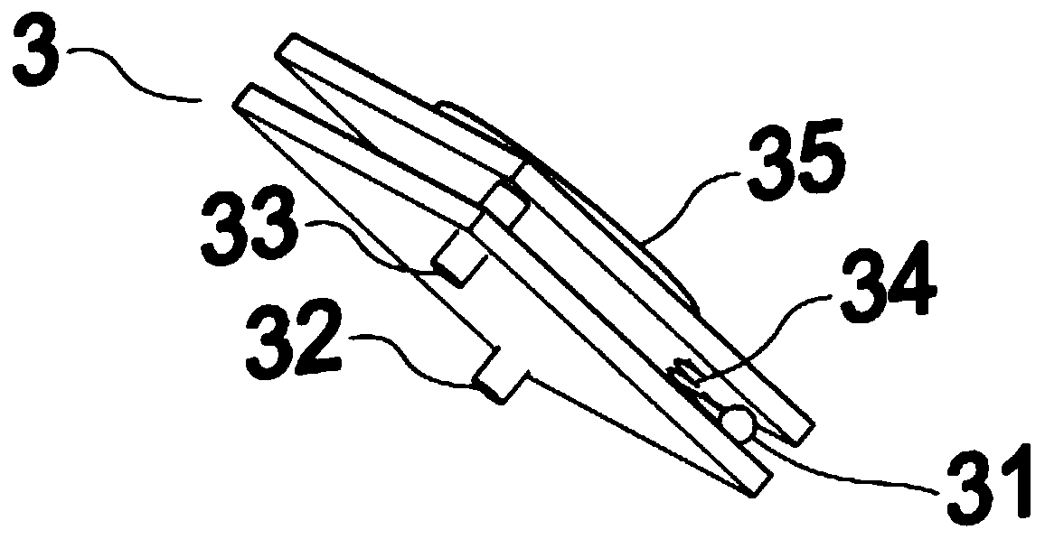
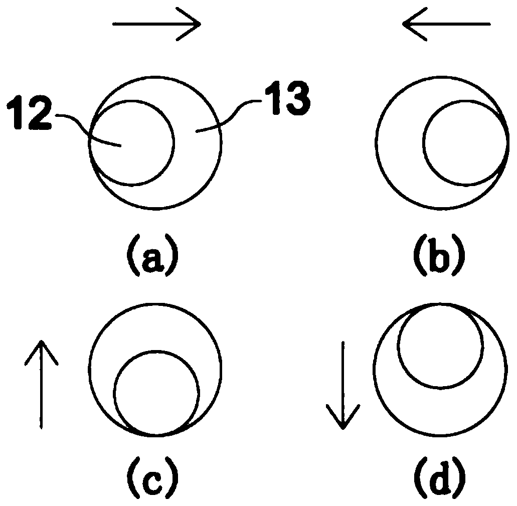
[0049] The schematic diagram of the third embodiment of the dual-beam laser processing optical system of the present invention is as follows Image 6 As shown, the difference from the first embodiment is that the scanning galvanometer group used only includes X galvanometer X scanning mirror. The common movement direction of the dual beam laser on the workpiece can only move left and right. Taking the auxiliary laser focusing spot in front and the main laser focusing spot in the back, it is used for preheating and auxiliary heating as an example. The positions of the main laser and auxiliary laser on the workpiece are as follows image 3 (a) and (b). The dual-beam laser processing optical system can be packaged and made into a handheld or mechanical moving arm for laser cleaning. Others such as the relative position control of the main laser and the auxiliary laser, and the structure of the mirror with adjustable deflection direction are consistent with t...


PUM


Abstract

The invention belongs to the field of laser processing, and discloses a double-beam laser processing optical system. The double-beam laser processing optical system comprises a pulse fiber laser (1) used for emitting main laser, a continuous laser (2) used for emitting auxiliary laser, a reflector (3) capable of adjusting deflection direction, a beam combiner (4), a focusing assembly and a laser scanning assembly, wherein the auxiliary laser is combined with a main laser through the reflector (3) capable of adjusting the deflection direction to form a double beam laser, the double beam laser is transmitted to a to-be-processed workpiece for the laser processing, and a relative position of a focusing light spot of an auxiliary laser and a focusing light spot of a main laser is kept unchanged all the time on a workpiece laser processing path. According to the system, the composition of components in the system and interaction relation among the components are improved, the auxiliary laser which the relative position of the focusing light spot always keeps unchanged with the focusing light spot of the main laser on the workpiece laser processing path is introduced, the double beam isrealized, and the problems of high price and the like of the high-power optical fiber laser can be overcome.

Description

technical field [0001] The invention belongs to the field of laser processing, and more specifically relates to a double-beam laser processing optical system. Background technique [0002] The fiber laser has a simple structure, small size, simple and reliable operation and maintenance, and does not require complex equipment such as water-cooled structures in semiconductor laser-pumped solid-state laser systems. Compared with lamp-pumped lasers, fiber lasers consume only about 1% of the electrical energy of lamp-pumped laser systems, and because optical fibers can only transmit fundamental spatial modes, the beam quality of fiber lasers is not affected by laser power operation. Fiber lasers are the most stable and easy-to-use of all solid-state lasers. Compared with traditional processing and other types of processing, high-power pulsed fiber lasers have obvious advantages. Nanosecond high-power pulsed fiber lasers have become the first choice for laser deep engraving and la...

Claims


Application Information

Patent Timeline
IPC IPC(8): B23K26/06B23K26/064
CPCB23K26/0604B23K26/064B23K26/0643
Inventor 秦应雄李玫瑰唐霞辉
Owner HUAZHONG UNIV OF SCI & TECH
Why Eureka
Try Eureka