
Multi-disc waxing machine

A technology of wax machine and mounting plate, which is applied in the direction of cleaning machinery, grinding machine parts, surface polishing machine tools, etc. It can solve the problems of reducing the relative speed between the polishing wheel and the surface of the workpiece, reducing the effect of polishing and waxing, etc. Achieve the effect of good operation consistency, simple structure and good effect

Pending Publication Date: 2019-08-02
常州市英杰工具有限公司
View PDF1 Cites 0 Cited by
  • Summary
  • Abstract
  • Description
  • Claims
  • Application Information

AI Technical Summary

Problems solved by technology

Because of this structure, the polishing disc rotates with the rotating disc and does not rotate itself. When the polishing wheel adheres to the surface of the workpiece to produce resistance, the relative speed between the polishing wheel and the surface of the workpiece will be reduced, thereby reducing the polishing effect. The effect of waxing

Method used


Image

  • Multi-disc waxing machine
  • Multi-disc waxing machine
  • Multi-disc waxing machine

Examples


Embodiment 1)

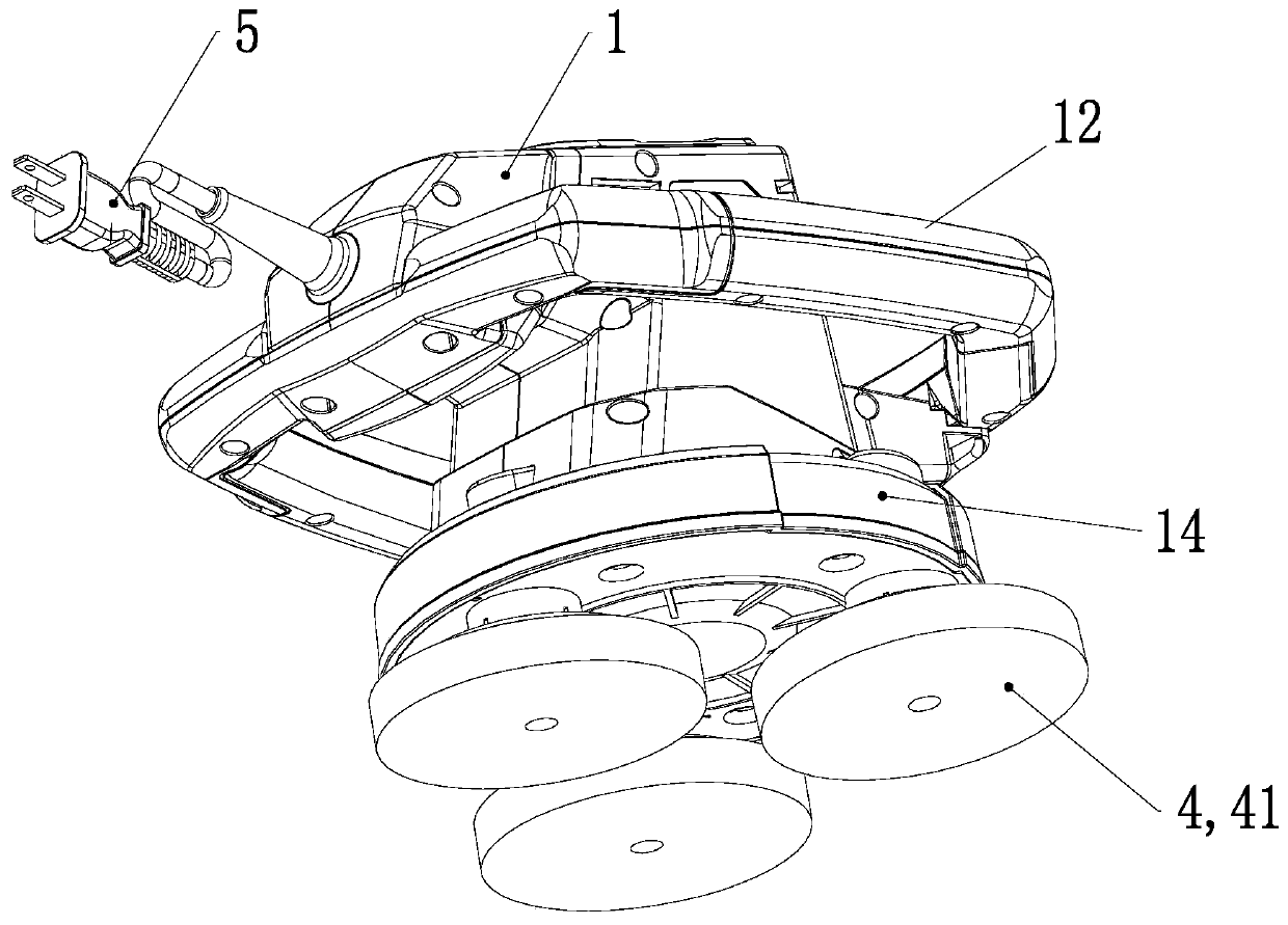
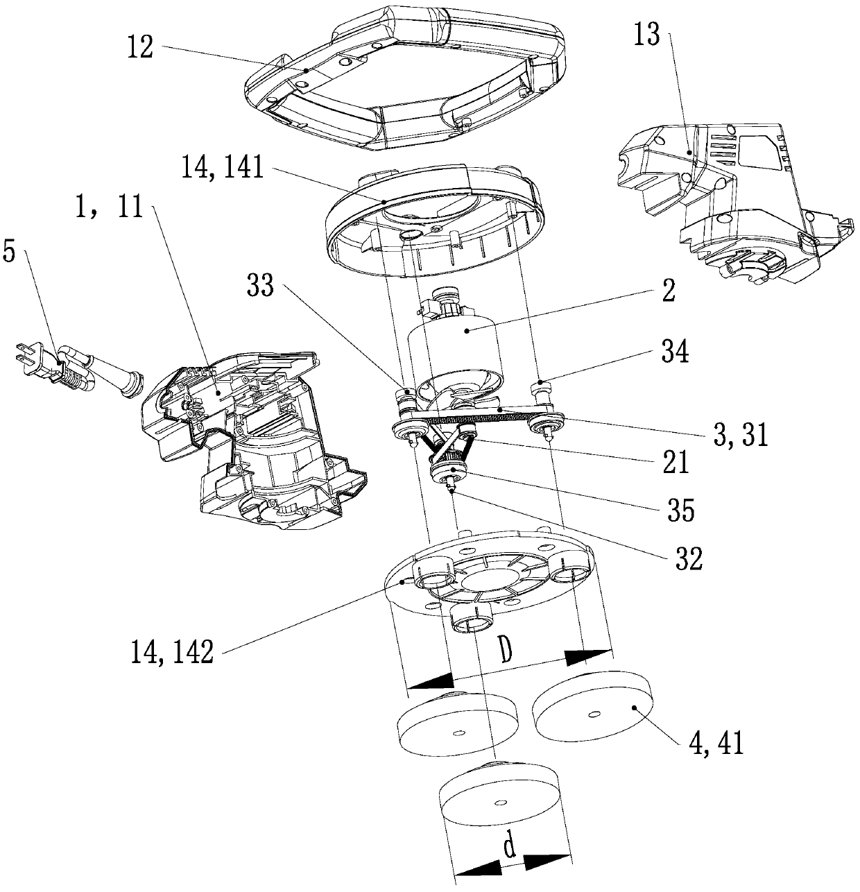
[0034] See Figure 1 to Figure 13 , The multi-disk waxing machine of the present invention includes a housing 1, a motor 2, a transmission assembly 3, a disc throwing assembly 4 and a power cord 5.

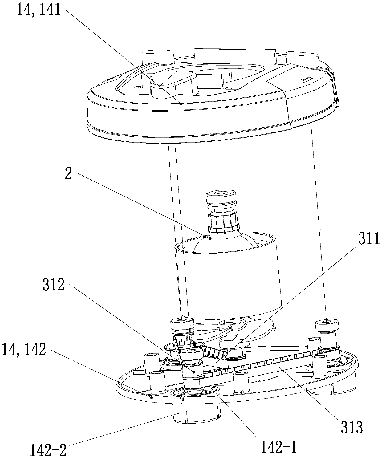
[0035] See Figure 1 to Figure 4 and Figure 10 to Figure 12 , the housing 1 includes a left housing 11, a handle 12, a right housing 13 and a mounting plate 14; the left housing 11 and the right housing 13 are fixedly connected to form a cavity structure, and the cavity has a downward opening. The handle 12 is ring-shaped, and the handle 12 is fixedly connected with the left housing 11 and the right housing 13 , and is arranged around the upper parts of the left housing 11 and the right housing 13 . The installation tray 14 includes an upper cover plate 141 of the installation tray and a lower base 142 of the installation tray. The lower base 142 of the installation disk is fixedly arranged on the lower part of the upper cover plate 141 of the installation disk from below, and...

Embodiment 2)

[0046] see Figure 15 , the basic structure of this embodiment is the same as that of Embodiment 1, the difference is that the transmission mode of this embodiment is a parallel transmission mode, and the corresponding pulleys and belts are adjusted accordingly according to the transmission mode: the parallel transmission mode is The motor output shaft 21 simultaneously drives a corresponding throwing disc 41 to rotate through three belts.

Embodiment 3)

[0048] see Figure 16 , the basic structure of this embodiment is the same as that of Embodiment 1, the difference is that the transmission mode of this embodiment is an envelope transmission mode, and the corresponding pulleys and belts are adjusted accordingly according to the transmission mode: the envelope transmission The method is that the motor output shaft 21 simultaneously drives three throwing discs 41 to rotate through one enveloping belt 314 . Both the inner and outer sides of the envelope belt 314 are provided with protruding teeth.


PUM


Abstract

The invention discloses a multi-disc waxing machine which comprises a shell, a motor, a transmission component, three to five groups of abrasive disc components and a power line, wherein the shell comprises a left shell, a handle, a right shell and a mounting disc; the power line is fixedly connected onto the shell; an operating switch is arranged on the handle; and the motor is mounted a cavity formed by the left shell and the right shell. The multi-disc waxing machine is characterized in that the transmission component is arranged in the cavity of the mounting disc; the abrasive disc components are arranged at equal angles in the circumferential direction of the mounting disc and are provided with the same structure; each of the abrasive disc components comprises an abrasive disc; and the motor drives the abrasive discs of the abrasive disc components through the transmission component to rotate.

Description

technical field [0001] The invention relates to the technical field of automobile and household waxing machines, in particular to a hand-held multi-disc waxing machine for automobiles and household use. Background technique [0002] The waxing machine for automobiles and households is mainly used for surface treatment such as washing, beauty, polishing, waxing, etc. of automobiles and furniture, which effectively improves work efficiency and work quality. Patent No. 201721345153.5 is a utility model patent "a hand-held car polishing machine", which includes a housing, a motor installed in the housing, and a polishing assembly located at the bottom of the housing and driven by the motor. The polishing assembly includes a rotating disc and a At least three polishing wheels (also known as throwing discs) uniformly arranged in the circumferential direction of the rotating disc, an eccentric connection is arranged between the rotating disc and the motor, and the motor drives the ...

Claims


Application Information

Patent Timeline
Patent Type & Authority Applications(China)
IPC IPC(8): B24B23/02B24B27/00B24B29/02B24B41/04B24B45/00B24B47/12B60S3/04A47L11/16A47L11/164
CPCB24B29/02B24B23/02B24B41/04B24B27/0076B24B47/12B24B45/00B60S3/048A47L11/16A47L11/164
Inventor 焦俊杰王文斌
Owner 常州市英杰工具有限公司
Learn More