
Orbit correction method and system of space laser interference gravitational wave detector

A technology of laser interference and orbit correction, which is applied in the field of aerospace science and technology, can solve problems such as few orbit correction methods, no calculation of orbit correction amount, no space for laser interference gravitational wave detector orbit correction, etc., to reduce fuel consumption, The effect of extending the task life

Active Publication Date: 2019-08-02
BEIHANG UNIV
View PDF10 Cites 5 Cited by
  • Summary
  • Abstract
  • Description
  • Claims
  • Application Information

AI Technical Summary

Problems solved by technology

However, there are still relatively few studies on orbit correction methods for space laser interferometric gravitational wave detectors
[0004] In the spacecraft orbit correction method proposed in the prior art, the focus is on the orbit correction control method without considering the calculation of the orbit correction amount. For the space laser interference gravitational wave detection task, the stability of the equilateral triangle configuration of the detector only needs to be guaranteed Within a certain range, there is no corresponding method to effectively correct the orbit of the space laser interference gravitational wave detector in the prior art

Method used


Image

  • Orbit correction method and system of space laser interference gravitational wave detector
  • Orbit correction method and system of space laser interference gravitational wave detector
  • Orbit correction method and system of space laser interference gravitational wave detector

Examples


Embodiment Construction

[0034] In order to make the purpose, technical solutions and advantages of the embodiments of the present invention clearer, the technical solutions in the embodiments of the present invention will be clearly and completely described below in conjunction with the drawings in the embodiments of the present invention. Obviously, the described embodiments It is a part of embodiments of the present invention, but not all embodiments. Based on the embodiments of the present invention, all other embodiments obtained by persons of ordinary skill in the art without creative efforts fall within the protection scope of the present invention.

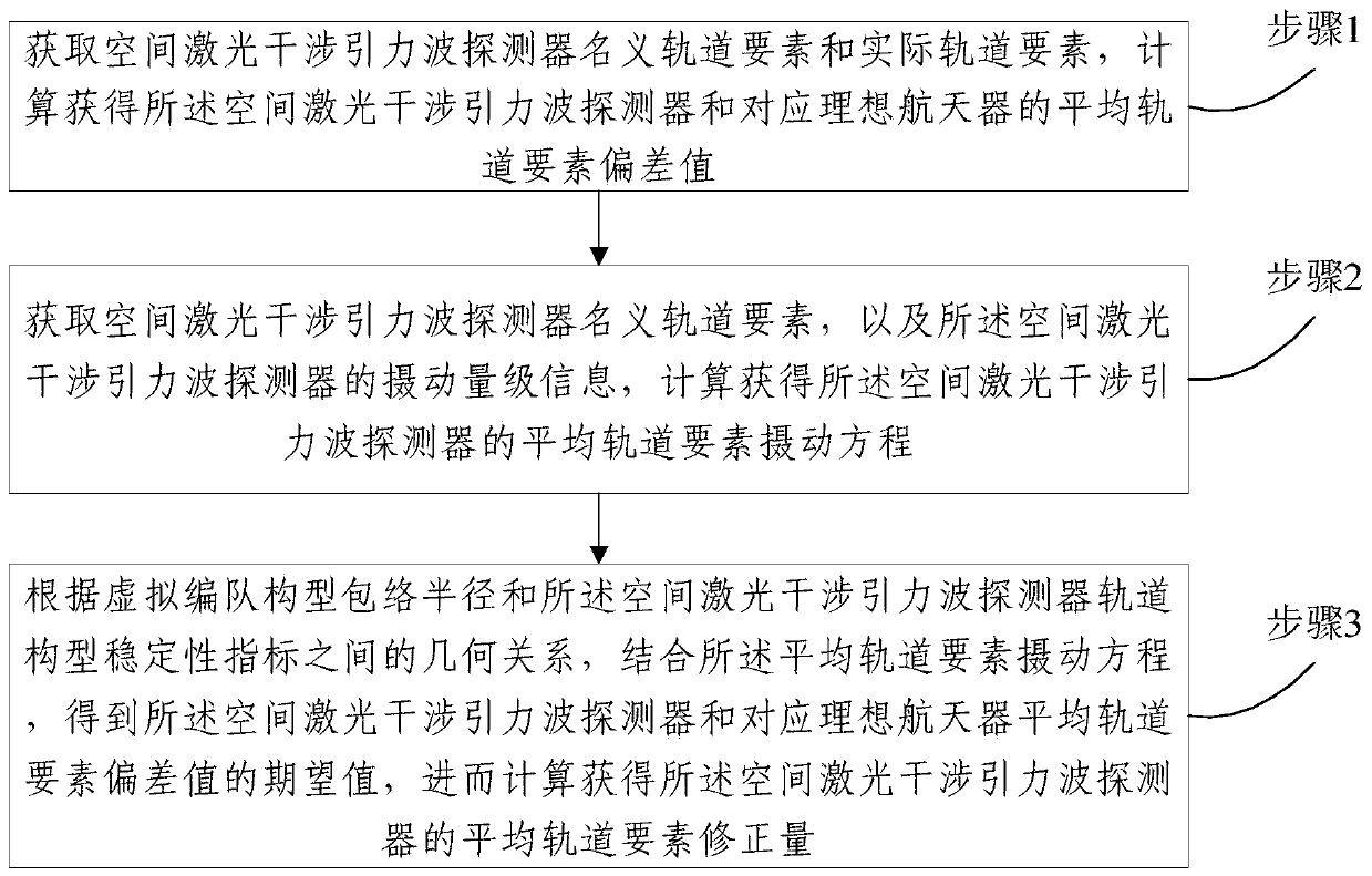
[0035] refer to figure 1 , figure 1 It is a schematic flow chart of the orbit correction method of the space laser interference gravitational wave detector provided by an embodiment of the present invention. The provided method includes:

[0036] Step 1, obtain the nominal orbital elements and actual orbital elements of the space laser interfere...


PUM


Abstract

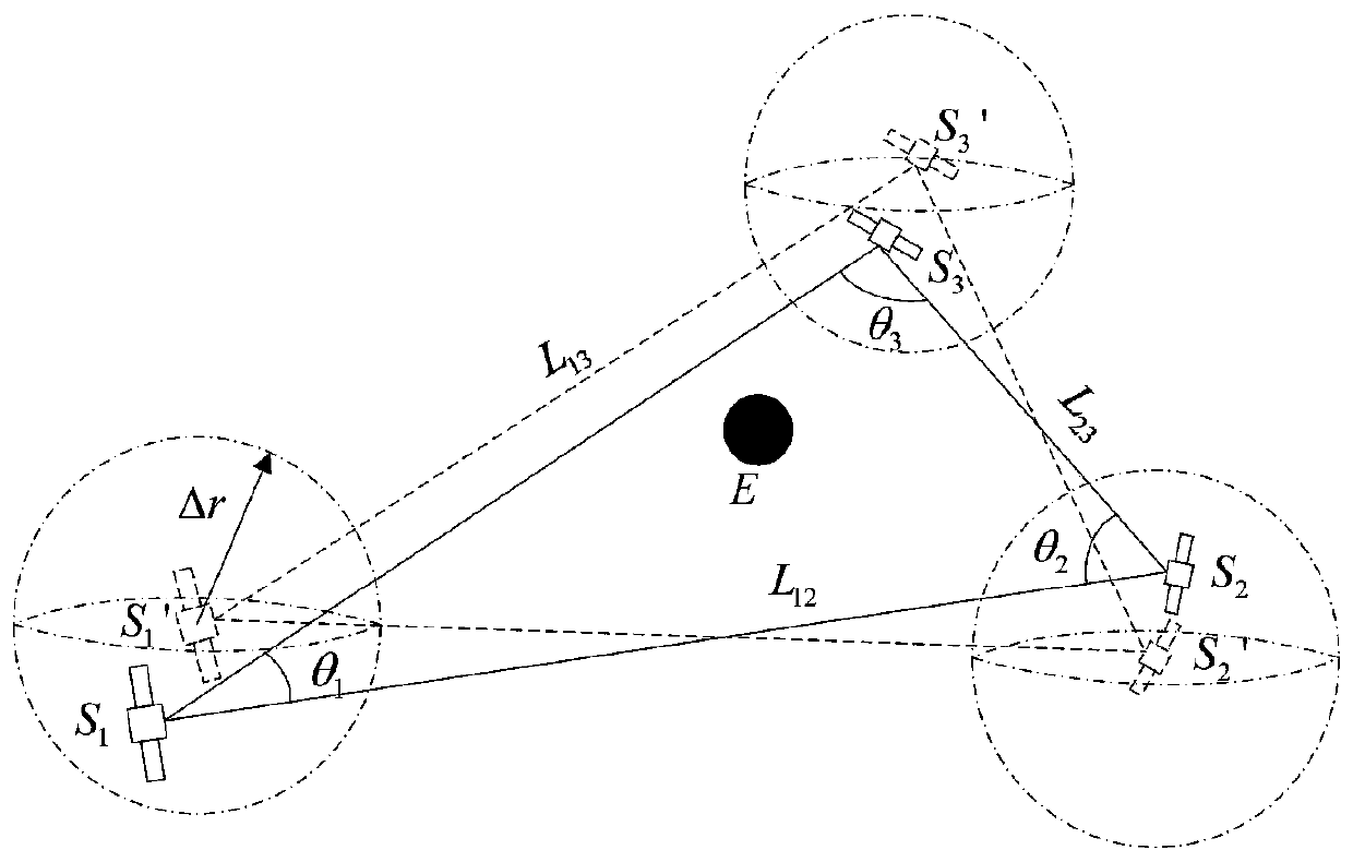
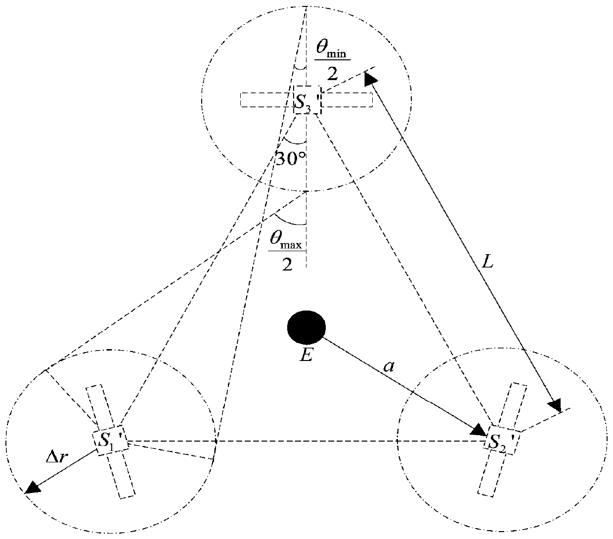
The embodiments of the invention provide an orbit correction method and system of a space laser interference gravitational wave detector. The orbit correction method comprises the steps: nominal orbitelements and actual orbit elements of the space laser interference gravitational wave detector are obtained, and the average orbit element deviation value of the space laser interference gravitational wave detector is calculated; the nominal orbit elements of the space laser interference gravitational wave detector and perturbation magnitude information of the space laser interference gravitational wave detector are obtained, and an average orbit element perturbation equation of the space laser interference gravitational wave detector is calculated; and according to the geometrical relationship between the virtual formation configuration envelope radius and orbit configuration stability indexes of the space laser interference gravitational wave detector, by combining with the average orbit element perturbation equation, the expected value of the average orbit element deviation value of the space laser interference gravitational wave detector is obtained, and then the average orbit element correction of the space laser interference gravitational wave detector is calculated. According to the orbit correction method, fuel consumption can be reduced, and the mission life is prolonged.

Description

technical field [0001] The invention relates to the technical field of aerospace science and technology, in particular to a method and system for orbit correction of a space laser interference gravitational wave detector. Background technique [0002] Gravitational waves are a famous prediction of general relativity. On February 11, 2016, the Laser Interferometer Gravitational-Wave Observatory (LIGO) of the United States announced that it had successfully observed the gravitational waves generated by the merger of double black holes, labeled as GW150914, and the gravitational waves were confirmed by astronomical observations. However, limited by the noise of the ground system and the arm length, the ground-based gravitational wave detection system can only detect high-frequency gravitational wave signals. In order to detect the medium and low frequency gravitational waves produced by supermassive black hole mergers and other astronomical events, ESA and NASA proposed to joi...

Claims


Application Information

Patent Timeline
IPC IPC(8): B64G1/24
CPCB64G1/242
Inventor 师鹏黄文涛章建程琦翔赵育善
Owner BEIHANG UNIV
Learn More