
Wind power generation equipment

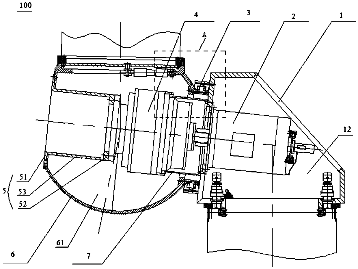
A technology for wind power generation equipment and generators, which is applied to wind power generation, wind turbines, wind turbine combinations, etc., can solve the problems of shortened life, excessive size, and deterioration of gear meshing conditions inside the gearbox, and achieves reduction in size and weight. , The effect of reducing radial load and reducing installation cost

Active Publication Date: 2019-08-02
STATE POWER INVESTMENT CORP RES INST
View PDF6 Cites 5 Cited by
  • Summary
  • Abstract
  • Description
  • Claims
  • Application Information

AI Technical Summary

Problems solved by technology

[0005] In the semi-direct drive wind turbines in the related art, in order to improve the size of the whole machine, the tail of the gearbox is installed on the front of the bracket, and the front end supports the wind wheel through a large bearing. The disadvantage of this structure is that in addition to its own weight, the gearbox bears the weight of the wind wheel The full load will inevitably lead to the overweight of the gearbox casing, which will increase the total weight of the unit, and the gear meshing condition inside the gearbox will deteriorate and shorten the life. The overall structure of the other types of semi-direct drive wind turbines is similar to the double-fed structure. The original or slightly modified mechanical transmission chain, that is, the structure of the main shaft, gearbox, and generator, is too large in size and weight for large semi-direct drive units, and there is room for improvement

Method used


Image

  • Wind power generation equipment
  • Wind power generation equipment

Examples


Embodiment Construction

[0025] Embodiments of the present application are described in detail below, examples of which are shown in the drawings, wherein the same or similar reference numerals denote the same or similar elements or elements having the same or similar functions throughout. The embodiments described below by referring to the figures are exemplary, and are only for explaining the present application, and should not be construed as limiting the present application.

[0026] In the description of the present application, it should be understood that the terms "center", "longitudinal", "transverse", "length", "width", "thickness", "upper", "lower", "front", " Back", "Left", "Right", "Vertical", "Horizontal", "Top", "Bottom", "Inner", "Outer", "Clockwise", "Counterclockwise", "Axial", The orientation or positional relationship indicated by "radial", "circumferential", etc. is based on the orientation or positional relationship shown in the drawings, and is only for the convenience of descri...


PUM


Abstract

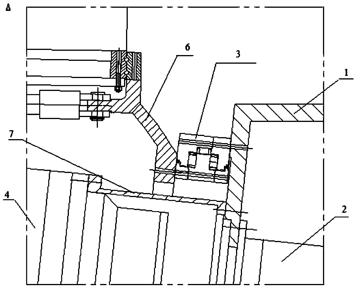
The application discloses wind power generation equipment. The wind power generation equipment comprises a wind wheel, a speed increasing box and a power generator; a wheel hub of the wind wheel is provided with a first accommodating cavity; the speed increasing box is mounted in the first accommodating cavity; an input shaft of the speed increasing box is in power coupling connection with the wheel hub; one of an input shaft of the power generator and an output shaft of the speed increasing box is arranged out of the other of the input shaft of the power generator and the output shaft of thespeed increasing box in a sleeving manner, and the input shaft of the power generator and the output shaft of the speed increasing box are in power coupling connection with each other. According to the wind power generation equipment disclosed by the invention, the axial length of the overall wind power generation equipment can be greatly reduced and the radial load between the wind wheel and thepower generator can be reduced by redesigning the structural positions and the connecting structures of the wheel hub, the speed increasing box and the power generator, so that the size and the weightof the overall wind power generation equipment can be reduced; and the installation cost can be reduced.

Description

technical field [0001] The present application belongs to the technical field of wind power generation, and in particular, relates to a wind power generation device. Background technique [0002] With the development of wind power generator technology, the structure of wind power generators tends to be larger, and the size of the nacelle becomes larger and larger. For example, the length of the nacelle of a 3MW double-fed unit reaches 15 meters, and the length of the nacelle of a 10MW double-fed unit reaches 20 meters. Both reach 8 meters, and the length of the 5MW direct-drive unit cabin also reaches 10 meters, and the height and width both reach 6.5 meters, followed by a larger tower size. [0003] When the power exceeds 5MW, in order to reduce the size, weight and cost of the unit, it is generally considered to use a direct drive unit, that is, the structure of the main shaft, gearbox and coupling without an intermediate transmission chain, and the wind wheel directly dri...

Claims


Application Information

Patent Timeline
Patent Type & Authority Applications(China)
IPC IPC(8): F03D15/00F03D80/00F03D9/25
CPCF03D9/25F03D15/00F03D80/00Y02E10/72
Inventor 李高盛严帅曹菡鲁仰辉卢华兴
Owner STATE POWER INVESTMENT CORP RES INST
Learn More