

Sample application device for detecting aflatoxin based on thin-layer analysis method
A kind of technology of aflatoxin and sample spotting device, which is applied in the direction of measuring device, analysis material, material separation, etc., can solve the problems such as easy deviation of spot position, low sample spotting efficiency, and influence of aflatoxin TLC detection, etc., to achieve Effects of improving usability and improving sampling efficiency
- Summary
- Abstract
- Description
- Claims
- Application Information
AI Technical Summary
Problems solved by technology
Method used
Image

Examples
Embodiment Construction
[0024] The present invention is described in further detail now in conjunction with accompanying drawing. These drawings are all simplified schematic diagrams, which only illustrate the basic structure of the present invention in a schematic manner, so they only show the configurations related to the present invention.
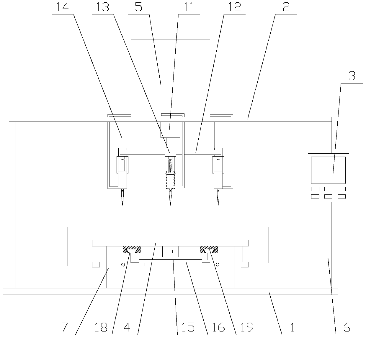
[0025] Such as figure 1 As shown, a sample spotting device for aflatoxin detection based on thin-layer analysis, including a base 1, a top plate 2, a controller 3, a flat plate 4, a correction mechanism, a sample spotting mechanism, a material box 5, two Side plate 6 and four legs 7, the side plate 6 is fixed above the base 1, the top plate 2 is erected on the two side plates 6, the controller 3 is fixed on one of the side plates 6, the The controller 3 is provided with a PLC, the material box 5 is fixed above the top plate 2, the four corners of the flat plate 4 are respectively fixed above the base 1 by four legs 7, and the correction mechanism is located b...
PUM
 Abstract
Description
Claims
Application Information