
A microfluidic chip spotting machine and spotting method

A microfluidic chip and spotting technology, applied in chemical instruments and methods, preparation of test samples, and laboratory containers, etc., can solve problems such as unmarkable, vibration, unfavorable continuous production, etc., to prevent missed detection Unqualified products, guaranteed sample quality, and beneficial to the effect of continuous production

Active Publication Date: 2020-11-06
威海迈维特智能识别技术有限公司
View PDF2 Cites 0 Cited by
  • Summary
  • Abstract
  • Description
  • Claims
  • Application Information

AI Technical Summary

Problems solved by technology

[0003] CN101839688B discloses a machine vision-based real-time detection system for the biochip spotting process. The detection system is configured on a biochip spotting device. Refer to paragraph 0075 of the specification of this document. The digital camera moves with the motion of the spotting head , the sampling head moves quickly on the x-y platform, and after arriving at the designated position, make a short pause period, then rely on the piezoelectric principle to place samples, and then do a short waiting period to collect the image taken by the image capture device and analyze the image , and then, run to the next designated point, continue to repeat the above "pause-printing-wait-shoot-start" process, the pictures taken by the image capture device are used to detect individual leaks on the biochip, deformed shapes, or Quantitative detection results can be given for most points with a large difference in point size, which overcomes the shortcomings of manual detection, which are prone to fatigue, strong subjectivity, and fuzzy results.
However, the machine vision-based real-time detection system for the biochip sampling process has the following disadvantages: (1) multiple biochips are placed in a chip storage tray, and the grooves for storing biochips on the chip storage tray are connected with the biochips. There is a gap of 0.2-0.3mm between the chip deposits. When a biochip has finished spotting, in the subsequent process of spotting biochips on the same chip storage tray, the spotting will cause the vibration of the biochip and cause the chip to be damaged. Vibration of the storage tray, which may cause deformation of the sample that has been printed. In this detection system, after the digital camera takes a picture of the biochip that has been sampled, the sample on the biochip may still be deformed due to subsequent sample placement. , so the image taken by the system is not the final state of the biochip after spotting, and is inaccurate; (2) In the actual spotting process, in order to ensure the positioning accuracy of the biochip, the camera needs to take pictures of the biochip before spotting to determine its coordinate position (referring to CN102636378A), in this inspection system, because the digital camera moves along with the movement of the sample head, so after the camera takes pictures, it needs to wait for the point sample, resulting in the shooting of the digital camera and the point sample head. It is not conducive to continuous production, and the sampling efficiency is low; (3) the detection system can only perform statistical analysis on the qualification rate of the sampling, but cannot mark the unqualified products on the chip storage tray in real time. Unqualified products cannot be removed in time; (4) The camera can only take the vertical projection of the biochip, and cannot detect the thickness of the sample, so it cannot detect the dripping amount of the sample

Method used


Image

  • A microfluidic chip spotting machine and spotting method
  • A microfluidic chip spotting machine and spotting method
  • A microfluidic chip spotting machine and spotting method

Examples


Embodiment Construction

[0024] In order to clearly illustrate the technical features of this solution, the specific implementation of the present invention will be further described below according to the accompanying drawings.

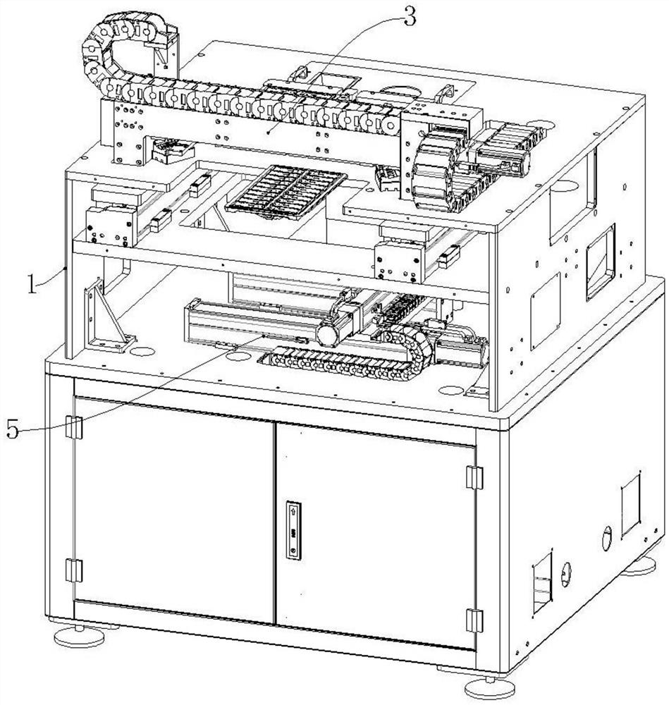
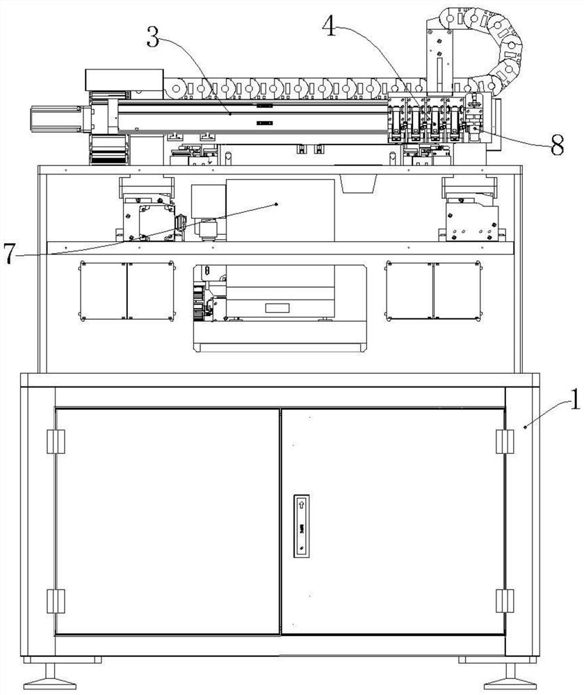
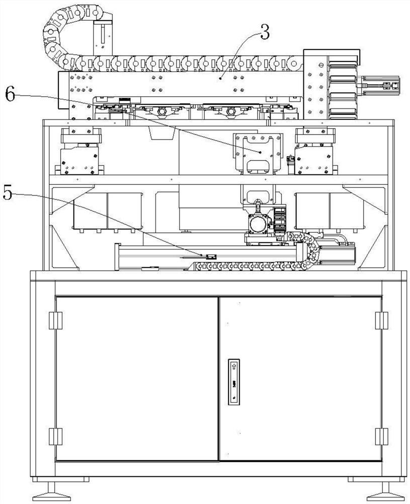
[0025] Such as Figure 1-Figure 6 As shown, a microfluidic chip pointing machine includes a frame 1, a fixture 2, a first xy linear module 3, a sampling head 4, a second xy linear module 5, a camera 6 and a weighing device 7, not Qualified product marking device 8 and waste liquid box 9.

[0026] Fixture 2 is set on Rack 1 as Figure 4 As shown, there are two sets of clamps 2, capable of clamping two chip storage trays 11 at the same time. The first xy linear module 3 is installed on the rack 1, such as Figure 5 As shown, both the sampling head 4 and the defective product marking device 8 are connected to the first xy linear module 3, and there are four sampling heads 4. In this embodiment, the defective product marking device 8 is an inkjet printer. The effect of the ...


PUM


Abstract

The invention relates to the field of biochip sample application equipment, in particular to a micro-fluidic chip sample application machine and sample application method. The micro-fluidic chip sample application machine comprises a rack, fixtures, a first xy linear module, a sample application head, a second xy linear module, a camera and a weighing device, wherein the fixtures are arranged on the rack, and at least two sets of fixtures are provided; the first xy linear module is installed on the rack, and the sample application head is connected with the first xy linear module; the second xy linear module is installed on the rack, and the camera is connected with the second xy linear module; and the weighing device is arranged on the rack. The micro-fluidic chip sample application machine provided by the invention drives the sample application head and the camera to move through the first xy linear module and the second xy linear module respectively, while the sample application head performs sample application, the camera can perform image collection, thereby facilitating the continuous production and ensuring high sample application efficiency; and after the sample applicationof all micro-fluidic chips on a chip storage disk is completed, the camera then detects the chips on the chip storage disk, thereby preventing the leak detection of unqualified products and ensuringthe sample application quality.

Description

technical field [0001] The invention relates to the field of biochip spotting equipment, in particular to a microfluidic chip spotting machine and a spotting method. Background technique [0002] Microfluidics integrates the basic operation units such as sample preparation, reaction, separation, and detection in the biological, chemical, and medical analysis processes into a micron-scale chip to automatically complete the entire analysis process. Due to its great potential in the fields of biology, chemistry, and medicine, it has developed into a new research field interdisciplinary in biology, chemistry, medicine, fluid, electronics, materials, and machinery. The shape of the microfluidic chip is a 75*25*2 PMMA plate with multiple channels inside. The chip is coated with 1-4 kinds of antigen antibody proteins, such as creatine kinase isoenzyme (CK-MB), which can Diagnosis of early myocardial infarction. When working, the spotting machine drops human serum samples onto the...

Claims


Application Information

Patent Timeline
Patent Type & Authority Patents(China)
IPC IPC(8): G01N35/10G01N1/28G01B11/00B01L3/00
CPCB01L3/5027G01B11/002G01N1/28G01N35/10
Inventor 韩军
Owner 威海迈维特智能识别技术有限公司
Features
  • Generate Ideas
  • Intellectual Property
  • Life Sciences
  • Materials
  • Tech Scout
  • Unparalleled Data Quality
  • Higher Quality Content
  • 60% Fewer Hallucinations
Learn More